
How to Use MKE-S13: Examples, Pinouts, and Specs

 Design with MKE-S13 in Cirkit Designer
Introduction
The MKE-S13 is a compact, high-performance microcontroller developed by MakerLab. It is designed for embedded applications, offering low power consumption and a variety of integrated peripherals to enable efficient control and communication. The MKE-S13 is ideal for projects requiring precise control, data processing, and connectivity in a small form factor.
Explore Projects Built with MKE-S13
 Open Project in Cirkit Designer
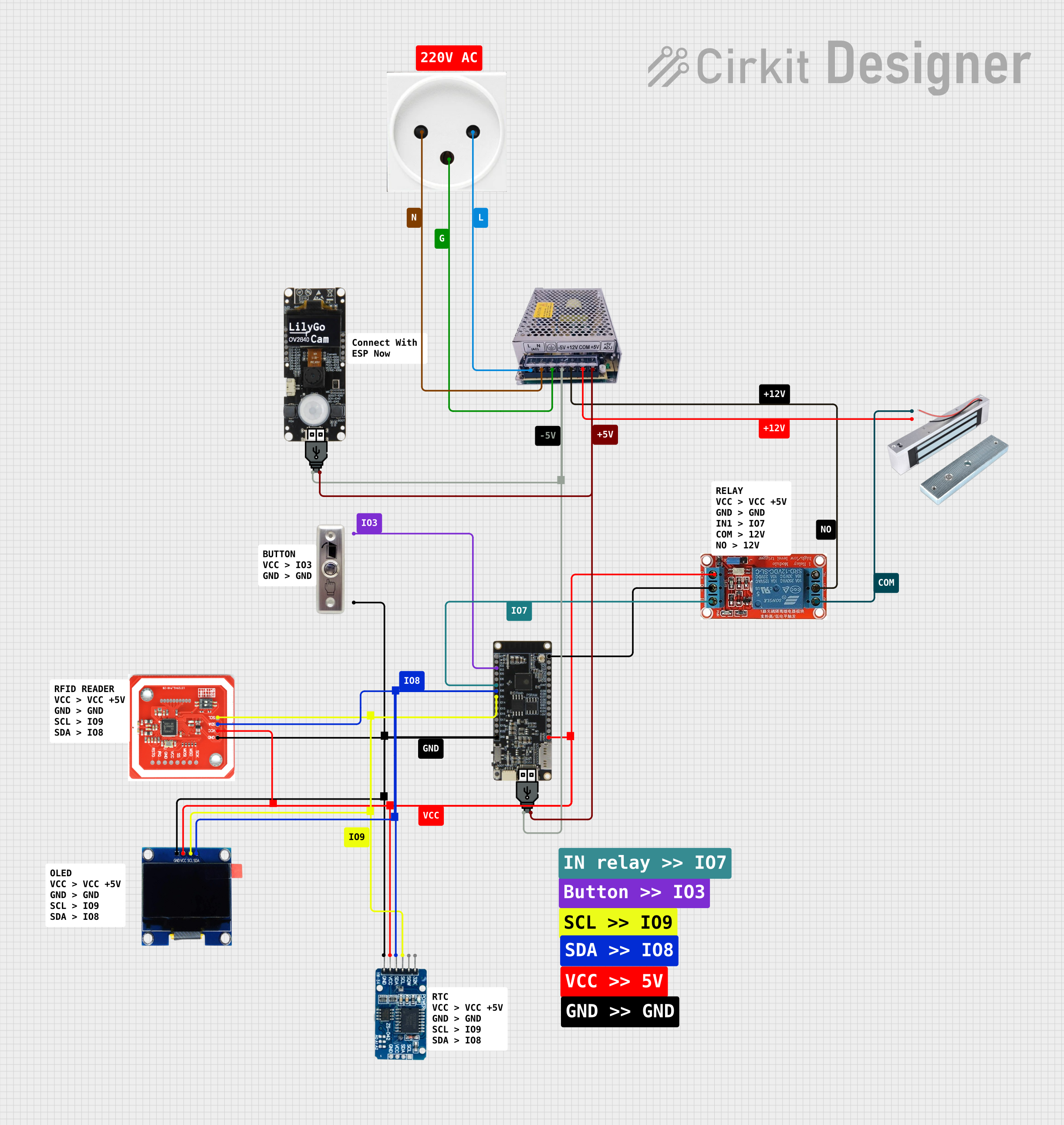 Open Project in Cirkit Designer
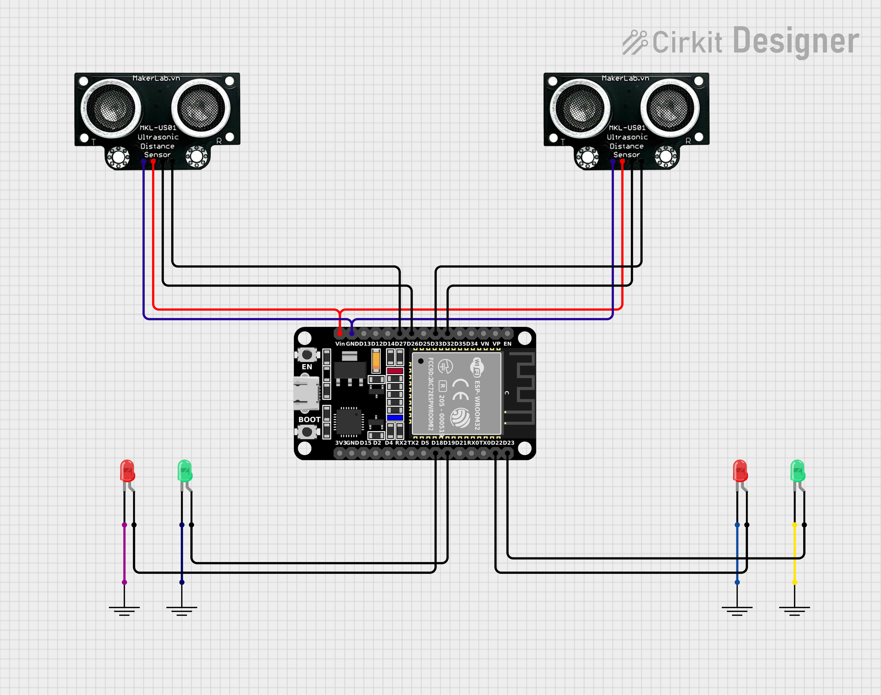 Open Project in Cirkit Designer
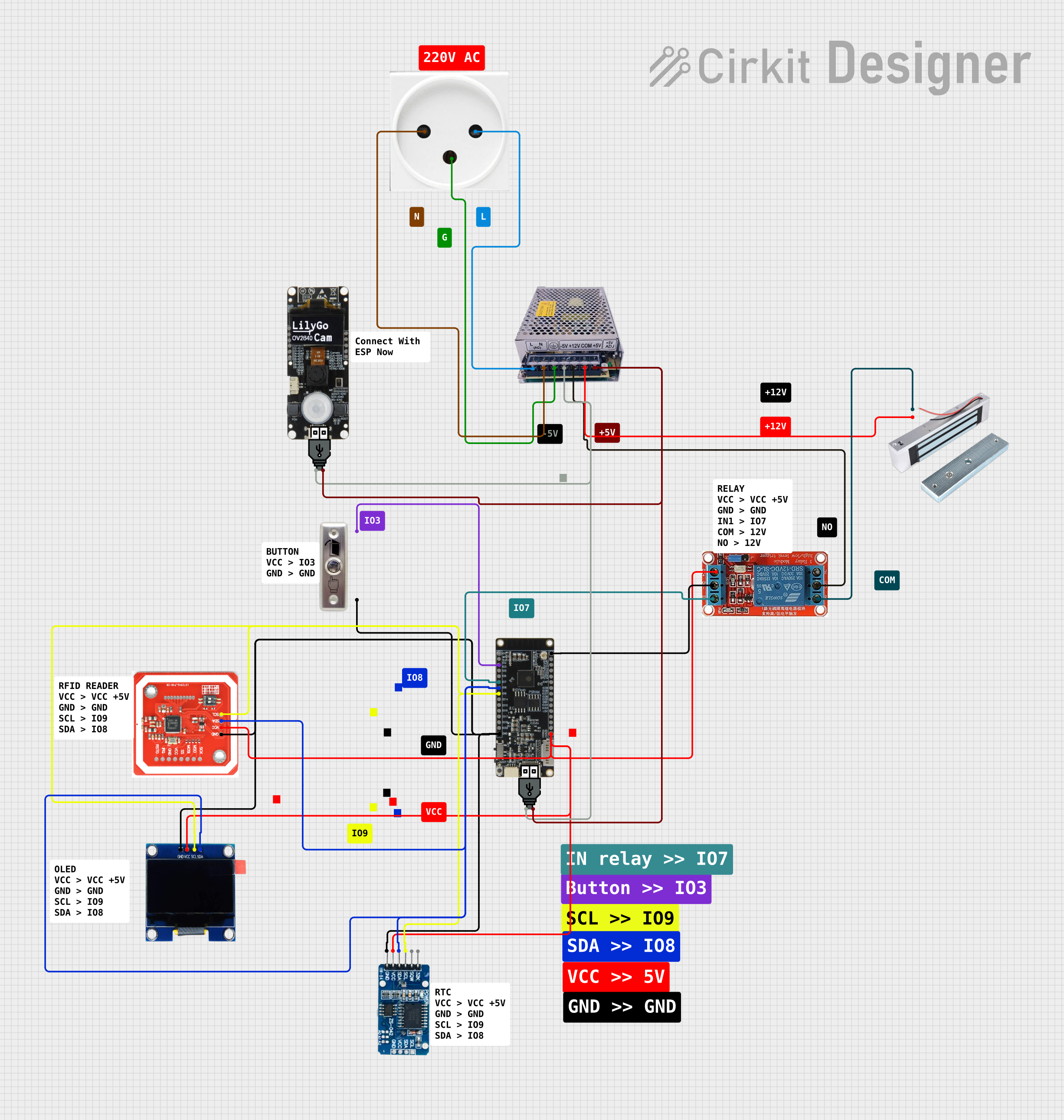 Open Project in Cirkit Designer
Explore Projects Built with MKE-S13
Open Project in Cirkit DesignerOpen Project in Cirkit DesignerOpen Project in Cirkit DesignerOpen Project in Cirkit DesignerCommon Applications and Use Cases
- IoT devices and smart home systems
- Industrial automation and control systems
- Wearable electronics
- Robotics and motor control
- Data acquisition and sensor interfacing
- Low-power portable devices
Technical Specifications
The MKE-S13 microcontroller is built to deliver reliable performance while maintaining energy efficiency. Below are its key technical specifications:
| Parameter | Specification |
|---|---|
| Processor Core | ARM Cortex-M4, 32-bit |
| Operating Frequency | Up to 72 MHz |
| Flash Memory | 128 KB |
| SRAM | 32 KB |
| GPIO Pins | 24 configurable pins |
| Communication Interfaces | UART, SPI, I2C, CAN |
| ADC Resolution | 12-bit, 8 channels |
| PWM Channels | 6 |
| Operating Voltage | 1.8V to 3.6V |
| Power Consumption | 5 µA in standby mode |
| Package Type | QFN-32 |
| Temperature Range | -40°C to +85°C |
Pin Configuration and Descriptions
The MKE-S13 features a 32-pin QFN package. Below is the pin configuration and description:
| Pin Number | Pin Name | Function | Description |
|---|---|---|---|
| 1 | VDD | Power Supply | Positive power supply (1.8V to 3.6V) |
| 2 | GND | Ground | Ground connection |
| 3 | PA0 | GPIO/ADC Channel 0 | General-purpose I/O or ADC input |
| 4 | PA1 | GPIO/ADC Channel 1 | General-purpose I/O or ADC input |
| 5 | PA2 | GPIO/UART TX | General-purpose I/O or UART transmit |
| 6 | PA3 | GPIO/UART RX | General-purpose I/O or UART receive |
| 7 | PB0 | GPIO/PWM Channel 0 | General-purpose I/O or PWM output |
| 8 | PB1 | GPIO/PWM Channel 1 | General-purpose I/O or PWM output |
| 9 | PB2 | GPIO/SPI SCK | General-purpose I/O or SPI clock |
| 10 | PB3 | GPIO/SPI MISO | General-purpose I/O or SPI data input |
| 11 | PB4 | GPIO/SPI MOSI | General-purpose I/O or SPI data output |
| 12 | PB5 | GPIO/I2C SCL | General-purpose I/O or I2C clock |
| 13 | PB6 | GPIO/I2C SDA | General-purpose I/O or I2C data |
| 14-31 | PC0-PC17 | GPIO | General-purpose I/O pins |
| 32 | NRST | Reset | Active-low reset input |
Usage Instructions
The MKE-S13 microcontroller is versatile and can be used in a wide range of applications. Below are the steps and best practices for using the component in a circuit:
How to Use the MKE-S13 in a Circuit
- Power Supply: Connect the VDD pin to a stable power source (1.8V to 3.6V) and the GND pin to ground.
- Reset: Use the NRST pin to reset the microcontroller. This pin should be pulled high during normal operation.
- GPIO Configuration: Configure the GPIO pins as input or output based on your application. Unused pins should be left floating or pulled to ground through a resistor.
- Communication Interfaces:
- Use UART for serial communication with external devices.
- Use SPI or I2C for interfacing with sensors, displays, or other peripherals.
- ADC and PWM: Utilize the ADC channels for analog signal acquisition and the PWM channels for motor control or signal generation.
- Programming: Program the microcontroller using an appropriate development environment (e.g., Keil, STM32CubeIDE) and a compatible programmer/debugger.
Important Considerations and Best Practices
- Decoupling Capacitors: Place a 0.1 µF ceramic capacitor close to the VDD pin to filter out noise.
- Clock Source: Use the internal oscillator or connect an external crystal oscillator for precise timing.
- Low Power Mode: Leverage the standby mode to reduce power consumption in battery-powered applications.
- Pin Protection: Avoid exceeding the voltage and current ratings of the pins to prevent damage.
- Debugging: Use the SWD (Serial Wire Debug) interface for debugging and firmware updates.
Example: Connecting the MKE-S13 to an Arduino UNO
The MKE-S13 can communicate with an Arduino UNO via UART. Below is an example Arduino sketch to send data to the MKE-S13:
// Example: Sending data from Arduino UNO to MKE-S13 via UART

void setup() {
  Serial.begin(9600); // Initialize UART communication at 9600 baud rate
}

void loop() {
  Serial.println("Hello, MKE-S13!"); // Send a message to the MKE-S13
  delay(1000); // Wait for 1 second before sending the next message
}
Troubleshooting and FAQs
Common Issues and Solutions
Microcontroller Not Powering On
- Cause: Incorrect power supply voltage or missing decoupling capacitor.
- Solution: Ensure the VDD pin is supplied with 1.8V to 3.6V and add a 0.1 µF capacitor near the pin.
Communication Failure
- Cause: Incorrect baud rate or wiring.
- Solution: Verify the baud rate settings and ensure proper connections for UART, SPI, or I2C.
ADC Not Reading Correctly
- Cause: Noise or incorrect reference voltage.
- Solution: Use a stable reference voltage and add filtering capacitors to the ADC input.
Microcontroller Not Responding
- Cause: Firmware issue or improper reset.
- Solution: Reprogram the microcontroller and ensure the NRST pin is functioning correctly.
FAQs
Q: Can the MKE-S13 operate at 5V?
A: No, the MKE-S13 operates within a voltage range of 1.8V to 3.6V. Exceeding this range may damage the component.Q: Does the MKE-S13 support external interrupts?
A: Yes, the GPIO pins can be configured to trigger external interrupts.Q: What is the maximum clock frequency of the MKE-S13?
A: The MKE-S13 can operate at a maximum clock frequency of 72 MHz.Q: How can I reduce power consumption?
A: Use the standby mode and disable unused peripherals to minimize power consumption.
This concludes the documentation for the MKE-S13 microcontroller. For further assistance, refer to the official MakerLab datasheet or contact technical support.