Cirkit Designer Logo
Cirkit Designer
Your all-in-one circuit design IDE
Home / 
Component Documentation

How to Use Motor Driver - N-Mos PWM Trigger : Examples, Pinouts, and Specs

Image of Motor Driver - N-Mos PWM Trigger
Cirkit Designer LogoDesign with Motor Driver - N-Mos PWM Trigger in Cirkit Designer

Introduction

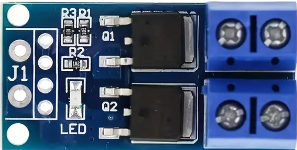
The Motor Driver - N-Mos PWM Trigger is an electronic component designed to control the speed and direction of a motor using an N-channel MOSFET and Pulse Width Modulation (PWM) signals. This driver is commonly used in robotics, automotive applications, and various DIY projects where precise motor control is required.

Explore Projects Built with Motor Driver - N-Mos PWM Trigger

Use Cirkit Designer to design, explore, and prototype these projects online. Some projects support real-time simulation. Click "Open Project" to start designing instantly!
ESP32-Controlled Dual Motor Driver with Optical Encoder Feedback
Image of Copy of Mobile Robot System with Speed and Position Control Using ESP32: A project utilizing Motor Driver - N-Mos PWM Trigger  in a practical application
This circuit is designed to control two DC motors using an L298N Dual Motor Driver Module, which receives PWM control signals from an ESP32 microcontroller. The motors' rotational movement can be monitored by two Optical Encoder Sensor Modules connected to the ESP32. Power is supplied by a 4 x AAA battery mount, with the battery's positive terminal connected to the motor driver's 12V input and the negative terminal to the common ground.
Cirkit Designer LogoOpen Project in Cirkit Designer
Arduino Nano Controlled Dual Motor Driver Circuit with Buck Converter Power Management
Image of lfr1: A project utilizing Motor Driver - N-Mos PWM Trigger  in a practical application
This circuit is designed to control two DC gearmotors using an Arduino Nano microcontroller and a dual-channel TB6612FNG motor driver. The Arduino Nano sends PWM signals to the motor driver to regulate the speed and direction of the motors. A step-down buck converter is used to provide the appropriate voltage levels from a LiPo battery to power the system.
Cirkit Designer LogoOpen Project in Cirkit Designer
Arduino-Controlled Dual Motor Driver with IR Sensing
Image of Line follower 14 IR Sensor channel: A project utilizing Motor Driver - N-Mos PWM Trigger  in a practical application
This circuit controls two DC motors using a TB6612FNG motor driver, which is interfaced with an Arduino Mega 2560 microcontroller. The Arduino provides PWM signals to control the speed and direction of the motors. Multiple IR sensors are connected to the Arduino's analog inputs, likely for sensing the environment or for line-following capabilities in a robot.
Cirkit Designer LogoOpen Project in Cirkit Designer
ESP32-Controlled Dual Motor Driver with Optical Encoder Feedback
Image of Mobile Robot System with Speed and Position Control Using ESP32: A project utilizing Motor Driver - N-Mos PWM Trigger  in a practical application
This circuit is designed to control two DC motors using an L298N Dual Motor Driver Module, which receives PWM control signals from an ESP32 microcontroller. The motors' rotational movement can be monitored by two Optical Encoder Sensor Modules, which are also interfaced with the ESP32. Power is supplied by a 4 x AAA battery mount, with the 12V line powering the motor driver and the 5V line stepping down to power the ESP32 and the encoder sensors.
Cirkit Designer LogoOpen Project in Cirkit Designer

Explore Projects Built with Motor Driver - N-Mos PWM Trigger

Use Cirkit Designer to design, explore, and prototype these projects online. Some projects support real-time simulation. Click "Open Project" to start designing instantly!
Image of Copy of Mobile Robot System with Speed and Position Control Using ESP32: A project utilizing Motor Driver - N-Mos PWM Trigger  in a practical application
ESP32-Controlled Dual Motor Driver with Optical Encoder Feedback
This circuit is designed to control two DC motors using an L298N Dual Motor Driver Module, which receives PWM control signals from an ESP32 microcontroller. The motors' rotational movement can be monitored by two Optical Encoder Sensor Modules connected to the ESP32. Power is supplied by a 4 x AAA battery mount, with the battery's positive terminal connected to the motor driver's 12V input and the negative terminal to the common ground.
Cirkit Designer LogoOpen Project in Cirkit Designer
Image of lfr1: A project utilizing Motor Driver - N-Mos PWM Trigger  in a practical application
Arduino Nano Controlled Dual Motor Driver Circuit with Buck Converter Power Management
This circuit is designed to control two DC gearmotors using an Arduino Nano microcontroller and a dual-channel TB6612FNG motor driver. The Arduino Nano sends PWM signals to the motor driver to regulate the speed and direction of the motors. A step-down buck converter is used to provide the appropriate voltage levels from a LiPo battery to power the system.
Cirkit Designer LogoOpen Project in Cirkit Designer
Image of Line follower 14 IR Sensor channel: A project utilizing Motor Driver - N-Mos PWM Trigger  in a practical application
Arduino-Controlled Dual Motor Driver with IR Sensing
This circuit controls two DC motors using a TB6612FNG motor driver, which is interfaced with an Arduino Mega 2560 microcontroller. The Arduino provides PWM signals to control the speed and direction of the motors. Multiple IR sensors are connected to the Arduino's analog inputs, likely for sensing the environment or for line-following capabilities in a robot.
Cirkit Designer LogoOpen Project in Cirkit Designer
Image of Mobile Robot System with Speed and Position Control Using ESP32: A project utilizing Motor Driver - N-Mos PWM Trigger  in a practical application
ESP32-Controlled Dual Motor Driver with Optical Encoder Feedback
This circuit is designed to control two DC motors using an L298N Dual Motor Driver Module, which receives PWM control signals from an ESP32 microcontroller. The motors' rotational movement can be monitored by two Optical Encoder Sensor Modules, which are also interfaced with the ESP32. Power is supplied by a 4 x AAA battery mount, with the 12V line powering the motor driver and the 5V line stepping down to power the ESP32 and the encoder sensors.
Cirkit Designer LogoOpen Project in Cirkit Designer

Common Applications and Use Cases

  • Robotics: Controlling the movement of robotic arms or wheels.
  • Automotive: Adjusting fan speeds or fuel pump control.
  • DIY Projects: Custom-built RC cars, drones, or automated machinery.

Technical Specifications

Key Technical Details

  • Operating Voltage: Typically ranges from 5V to 30V.
  • Continuous Current Rating: Up to 10A without a heatsink.
  • PWM Frequency Range: 1kHz to 20kHz recommended.
  • Logic Level Input: Compatible with 3.3V and 5V logic levels.

Pin Configuration and Descriptions

Pin Number Pin Name Description
1 V+ Motor power supply input (5V to 30V)
2 GND Ground connection
3 PWM PWM signal input for speed control
4 DIR Direction control input (Logic High or Low)
5 OUT+ Motor output positive
6 OUT- Motor output negative

Usage Instructions

How to Use the Component in a Circuit

  1. Power Supply Connection: Connect the motor power supply to the V+ and GND pins, ensuring that the voltage is within the specified operating range.
  2. Motor Connection: Attach the motor leads to the OUT+ and OUT- pins.
  3. Control Signal Connection: Connect the PWM signal to the PWM pin for speed control. The duty cycle of the PWM signal will determine the motor speed.
  4. Direction Control: Apply a logic high or low signal to the DIR pin to set the motor's rotation direction.

Important Considerations and Best Practices

  • Heat Dissipation: Ensure adequate cooling if the motor driver is expected to handle currents near the maximum rating.
  • PWM Signal: Use a microcontroller to generate the PWM signal with the appropriate frequency and duty cycle.
  • Protective Diodes: Include flyback diodes across the motor terminals to protect the driver from voltage spikes.
  • Isolation: Consider using optoisolators to separate the control circuit from the power circuit for added safety.

Example Code for Arduino UNO

// Define the pins connected to the motor driver
const int pwmPin = 3; // PWM input for speed control
const int dirPin = 4; // Direction control input

void setup() {
  // Set the motor driver pins as outputs
  pinMode(pwmPin, OUTPUT);
  pinMode(dirPin, OUTPUT);
}

void loop() {
  // Set motor direction to forward
  digitalWrite(dirPin, HIGH);
  // Ramp up the motor speed
  for (int speed = 0; speed <= 255; speed++) {
    analogWrite(pwmPin, speed);
    delay(10);
  }
  // Ramp down the motor speed
  for (int speed = 255; speed >= 0; speed--) {
    analogWrite(pwmPin, speed);
    delay(10);
  }
  // Change motor direction to reverse
  digitalWrite(dirPin, LOW);
  // Repeat the ramp up and ramp down process
  // ... (same as above)
}

Troubleshooting and FAQs

Common Issues

  • Motor not spinning: Check power supply connections and ensure the PWM signal is being sent.
  • Overheating: If the driver is too hot, reduce the load or improve heat dissipation.
  • Inconsistent speed control: Verify the PWM frequency and duty cycle are within specifications.

Solutions and Tips for Troubleshooting

  • Power Supply: Confirm that the voltage and current ratings are within the limits of the motor driver.
  • Signal Integrity: Use an oscilloscope to check the PWM and direction signals for proper levels and noise.
  • Connections: Ensure all connections are secure and free from shorts or opens.

FAQs

Q: Can I control two motors with this driver? A: No, this driver is designed for single motor control. Use separate drivers for each motor.

Q: What is the maximum PWM frequency I can use? A: While the driver can handle a range of frequencies, it is recommended to stay within 1kHz to 20kHz for optimal performance.

Q: How do I reverse the motor direction? A: Apply a logic high or low to the DIR pin to reverse the motor's direction. The actual logic level for forward or reverse may depend on the motor driver's design.

Remember to always consult the datasheet of the specific motor driver model you are using for the most accurate and detailed information.