How to Use LIS3DSH: Examples, Pinouts, and Specs
Introduction
The LIS3DSH is a low-power, 3-axis accelerometer that provides digital output via I2C or SPI interfaces. It is designed for motion sensing applications, offering features such as programmable full-scale ranges, high-resolution measurements, and built-in self-test capabilities. This versatile sensor is ideal for applications requiring precise motion detection, such as wearable devices, gaming peripherals, robotics, and industrial equipment.
Explore Projects Built with LIS3DSH

Explore Projects Built with LIS3DSH
Common Applications and Use Cases
- Motion tracking in wearable devices
- Gesture recognition in gaming controllers
- Vibration monitoring in industrial systems
- Tilt sensing in robotics and drones
- Step counting and activity monitoring in fitness devices
Technical Specifications
The LIS3DSH accelerometer is packed with features that make it suitable for a wide range of applications. Below are its key technical specifications:
| Parameter | Value |
|---|---|
| Supply Voltage (Vdd) | 1.8V to 3.6V |
| I/O Voltage (Vdd_IO) | 1.71V to 3.6V |
| Power Consumption | 2 µA in power-down mode, 11 µA in low-power mode |
| Measurement Range | ±2g, ±4g, ±6g, ±8g, ±16g (programmable) |
| Output Data Rate (ODR) | 3.125 Hz to 1.6 kHz |
| Interface | I2C (up to 400 kHz) or SPI (up to 10 MHz) |
| Resolution | 16-bit |
| Operating Temperature Range | -40°C to +85°C |
| Built-in Features | FIFO buffer, self-test, interrupt signals |
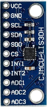
Pin Configuration and Descriptions
The LIS3DSH is typically available in a 16-pin LGA package. Below is the pinout and description:
| Pin | Name | Description |
|---|---|---|
| 1 | Vdd | Power supply (1.8V to 3.6V) |
| 2 | Vdd_IO | I/O voltage supply (1.71V to 3.6V) |
| 3 | GND | Ground |
| 4 | CS | SPI chip select (active low) |
| 5 | SCL/SPC | I2C clock line / SPI clock |
| 6 | SDA/SDI/SDO | I2C data line / SPI data input/output |
| 7 | INT1 | Interrupt 1 output |
| 8 | INT2 | Interrupt 2 output |
| 9-16 | NC | Not connected |
Usage Instructions
The LIS3DSH can be used in a variety of circuits, and its interface flexibility (I2C or SPI) makes it easy to integrate with microcontrollers like the Arduino UNO. Below are the steps to use the LIS3DSH in a circuit:
Connecting the LIS3DSH to an Arduino UNO (I2C Mode)
- Power the Sensor: Connect the
Vddpin to the Arduino's 3.3V pin andGNDto ground. - I2C Connections:
- Connect the
SCLpin of the LIS3DSH to the Arduino's A5 pin (I2C clock). - Connect the
SDApin of the LIS3DSH to the Arduino's A4 pin (I2C data).
- Connect the
- Pull-up Resistors: Add 4.7kΩ pull-up resistors on the
SCLandSDAlines if not already present. - Interrupts (Optional): Connect
INT1orINT2to any digital pin on the Arduino if you plan to use interrupts.
Sample Arduino Code
The following code demonstrates how to initialize the LIS3DSH in I2C mode and read acceleration data:
#include <Wire.h> // Include the Wire library for I2C communication

#define LIS3DSH_ADDR 0x1D // I2C address of the LIS3DSH
#define CTRL_REG4    0x20 // Control register 4 address
#define OUT_X_L      0x28 // X-axis acceleration data (low byte)

void setup() {
  Wire.begin(); // Initialize I2C communication
  Serial.begin(9600); // Initialize serial communication for debugging

  // Configure the LIS3DSH
  Wire.beginTransmission(LIS3DSH_ADDR);
  Wire.write(CTRL_REG4); // Select control register 4
  Wire.write(0x67); // Enable X, Y, Z axes and set ODR to 100 Hz
  Wire.endTransmission();
}

void loop() {
  int16_t x, y, z; // Variables to store acceleration data

  // Read X-axis acceleration (16-bit value)
  Wire.beginTransmission(LIS3DSH_ADDR);
  Wire.write(OUT_X_L | 0x80); // Set auto-increment bit for multi-byte read
  Wire.endTransmission(false);
  Wire.requestFrom(LIS3DSH_ADDR, 6); // Request 6 bytes (X, Y, Z data)

  if (Wire.available() == 6) {
    x = Wire.read() | (Wire.read() << 8); // Combine low and high bytes
    y = Wire.read() | (Wire.read() << 8);
    z = Wire.read() | (Wire.read() << 8);
  }

  // Print acceleration data to the serial monitor
  Serial.print("X: "); Serial.print(x);
  Serial.print(" Y: "); Serial.print(y);
  Serial.print(" Z: "); Serial.println(z);

  delay(100); // Delay for readability
}
Important Considerations and Best Practices
- Voltage Levels: Ensure the LIS3DSH operates within its specified voltage range (1.8V to 3.6V). Use a level shifter if interfacing with a 5V microcontroller.
- Pull-up Resistors: Always use pull-up resistors on the I2C lines if they are not already present on the board.
- Interrupts: Configure the interrupt pins (
INT1andINT2) for specific events like data-ready or free-fall detection. - Mounting: Securely mount the sensor to minimize vibrations and noise in measurements.
Troubleshooting and FAQs
Common Issues and Solutions
No Data Output:
- Ensure the LIS3DSH is powered correctly and the I2C/SPI connections are secure.
- Verify the I2C address (default is
0x1Dbut may vary depending on the SA0 pin configuration).
Incorrect or Noisy Readings:
- Check for proper grounding and minimize external vibrations.
- Verify that the sensor is configured with the correct full-scale range and output data rate.
I2C Communication Fails:
- Ensure pull-up resistors are present on the
SCLandSDAlines. - Check for address conflicts if multiple I2C devices are connected.
- Ensure pull-up resistors are present on the
FAQs
Q: Can the LIS3DSH be used with a 5V microcontroller?
A: Yes, but you must use a level shifter to step down the 5V signals to 3.3V for the LIS3DSH.
Q: How do I enable the self-test feature?
A: Write the appropriate value to the CTRL_REG4 register to enable the self-test mode. Refer to the datasheet for specific register settings.
Q: What is the maximum sampling rate of the LIS3DSH?
A: The LIS3DSH supports a maximum output data rate (ODR) of 1.6 kHz.
By following this documentation, you can effectively integrate and use the LIS3DSH accelerometer in your projects.