Cirkit Designer Logo
Cirkit Designer
Your all-in-one circuit design IDE
Home / 
Component Documentation

How to Use Sensor de efecto Hall Análogo: Examples, Pinouts, and Specs

Image of Sensor de efecto Hall Análogo
Cirkit Designer LogoDesign with Sensor de efecto Hall Análogo in Cirkit Designer

Introduction

The KY-035 is an analog Hall effect sensor manufactured by ESP32. It is designed to detect magnetic fields and output an analog voltage proportional to the strength of the magnetic field. This sensor is widely used in applications such as position sensing, current measurement, speed detection, and proximity sensing. Its compact design and ease of use make it a popular choice for hobbyists and professionals alike.

Explore Projects Built with Sensor de efecto Hall Análogo

Use Cirkit Designer to design, explore, and prototype these projects online. Some projects support real-time simulation. Click "Open Project" to start designing instantly!
Magnetic Field-Activated Solenoid Array with Arduino Control
Image of Railgun: A project utilizing Sensor de efecto Hall Análogo in a practical application
This circuit is designed to use Hall effect sensors for magnetic field detection, interfaced with an Arduino UNO microcontroller to control an array of solenoids through MOSFETs. It includes user interface elements such as a tactile switch and LED, and features flyback diodes for solenoid protection.
Cirkit Designer LogoOpen Project in Cirkit Designer
Arduino UNO-Based Sensor Monitoring System with IR and Hall Sensors
Image of BIOE4900: A project utilizing Sensor de efecto Hall Análogo in a practical application
This circuit uses an Arduino UNO to interface with an IR sensor and a Hall sensor. The IR sensor's output is connected to digital pin D2, while the Hall sensor's signal pin is connected to analog pin A0. The circuit is designed to read sensor data and potentially control an external device through the wire connector connected to digital pins D5 and D6.
Cirkit Designer LogoOpen Project in Cirkit Designer
Arduino UNO Magnetic Field Detector with Hall Sensor
Image of hall : A project utilizing Sensor de efecto Hall Análogo in a practical application
This circuit uses an Arduino UNO to read both analog and digital signals from a Hall magnetic sensor. The sensor's VCC and GND are connected to the Arduino's 5V and GND pins, respectively, while its analog and digital outputs are connected to the Arduino's A0 and D0 pins. The Arduino code reads these values and prints them to the serial monitor.
Cirkit Designer LogoOpen Project in Cirkit Designer
Arduino Nano ESP32 Hall Sensor Interface with LCD Display
Image of hall effect + speedometer: A project utilizing Sensor de efecto Hall Análogo in a practical application
This circuit includes a Hall sensor connected to an Arduino Nano ESP32 microcontroller, which is likely used to detect magnetic fields and send the data to the microcontroller on pin D12. The Arduino is also interfaced with an LCD display, with connections for power, ground, control (RS, E), and data (DB4-DB7) to display information. The absence of code suggests that the microcontroller's behavior is not defined in this context, but it is set up to read the Hall sensor and output to the LCD.
Cirkit Designer LogoOpen Project in Cirkit Designer

Explore Projects Built with Sensor de efecto Hall Análogo

Use Cirkit Designer to design, explore, and prototype these projects online. Some projects support real-time simulation. Click "Open Project" to start designing instantly!
Image of Railgun: A project utilizing Sensor de efecto Hall Análogo in a practical application
Magnetic Field-Activated Solenoid Array with Arduino Control
This circuit is designed to use Hall effect sensors for magnetic field detection, interfaced with an Arduino UNO microcontroller to control an array of solenoids through MOSFETs. It includes user interface elements such as a tactile switch and LED, and features flyback diodes for solenoid protection.
Cirkit Designer LogoOpen Project in Cirkit Designer
Image of BIOE4900: A project utilizing Sensor de efecto Hall Análogo in a practical application
Arduino UNO-Based Sensor Monitoring System with IR and Hall Sensors
This circuit uses an Arduino UNO to interface with an IR sensor and a Hall sensor. The IR sensor's output is connected to digital pin D2, while the Hall sensor's signal pin is connected to analog pin A0. The circuit is designed to read sensor data and potentially control an external device through the wire connector connected to digital pins D5 and D6.
Cirkit Designer LogoOpen Project in Cirkit Designer
Image of hall : A project utilizing Sensor de efecto Hall Análogo in a practical application
Arduino UNO Magnetic Field Detector with Hall Sensor
This circuit uses an Arduino UNO to read both analog and digital signals from a Hall magnetic sensor. The sensor's VCC and GND are connected to the Arduino's 5V and GND pins, respectively, while its analog and digital outputs are connected to the Arduino's A0 and D0 pins. The Arduino code reads these values and prints them to the serial monitor.
Cirkit Designer LogoOpen Project in Cirkit Designer
Image of hall effect + speedometer: A project utilizing Sensor de efecto Hall Análogo in a practical application
Arduino Nano ESP32 Hall Sensor Interface with LCD Display
This circuit includes a Hall sensor connected to an Arduino Nano ESP32 microcontroller, which is likely used to detect magnetic fields and send the data to the microcontroller on pin D12. The Arduino is also interfaced with an LCD display, with connections for power, ground, control (RS, E), and data (DB4-DB7) to display information. The absence of code suggests that the microcontroller's behavior is not defined in this context, but it is set up to read the Hall sensor and output to the LCD.
Cirkit Designer LogoOpen Project in Cirkit Designer

Common Applications

  • Position sensing in robotics and automation
  • Current measurement in power systems
  • Speed detection in motor control systems
  • Proximity sensing in security systems
  • Magnetic field strength measurement in scientific experiments

Technical Specifications

The KY-035 Hall effect sensor has the following key technical specifications:

Parameter Value
Manufacturer ESP32
Part ID KY-035
Operating Voltage 3.3V to 5V
Output Type Analog
Output Voltage Range 0V to Vcc (proportional to field)
Sensitivity High
Operating Temperature -40°C to +85°C
Dimensions 18mm x 10mm x 7mm

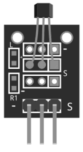
Pin Configuration and Descriptions

The KY-035 sensor has three pins, as described in the table below:

Pin Name Description
1 VCC Power supply pin (3.3V to 5V)
2 GND Ground pin
3 OUT Analog output pin (voltage proportional to magnetic field)
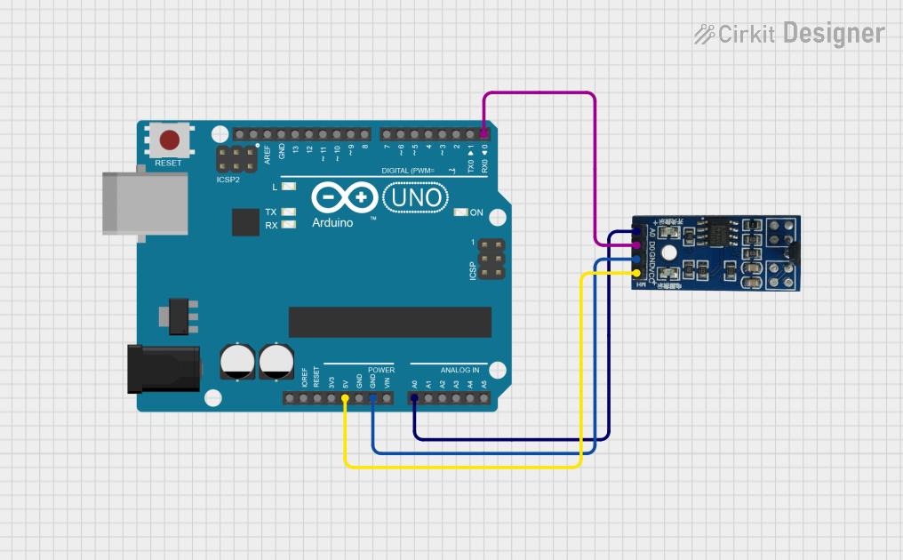
Usage Instructions

How to Use the KY-035 in a Circuit

  1. Power the Sensor: Connect the VCC pin to a 3.3V or 5V power source and the GND pin to the ground of your circuit.
  2. Read the Output: Connect the OUT pin to an analog input pin of your microcontroller (e.g., Arduino UNO or ESP32). The output voltage will vary based on the strength of the magnetic field.
  3. Place the Magnet: Position a magnet near the sensor. The closer the magnet, the higher the output voltage.

Important Considerations

  • Ensure the power supply voltage matches the sensor's operating range (3.3V to 5V).
  • Avoid exposing the sensor to extreme temperatures or strong physical impacts.
  • Use a decoupling capacitor (e.g., 0.1µF) between VCC and GND to reduce noise in the power supply.
  • For accurate readings, keep the sensor away from other magnetic sources that may interfere with measurements.

Example Code for Arduino UNO

Below is an example code snippet to read the analog output of the KY-035 using an Arduino UNO:

// Define the analog pin connected to the KY-035 OUT pin
const int hallSensorPin = A0;

void setup() {
  // Initialize serial communication for debugging
  Serial.begin(9600);
}

void loop() {
  // Read the analog value from the Hall effect sensor
  int sensorValue = analogRead(hallSensorPin);

  // Convert the analog value to voltage (assuming 5V reference)
  float voltage = sensorValue * (5.0 / 1023.0);

  // Print the voltage to the Serial Monitor
  Serial.print("Magnetic Field Voltage: ");
  Serial.print(voltage);
  Serial.println(" V");

  // Add a small delay for stability
  delay(500);
}

Notes for ESP32 Users

If using the KY-035 with an ESP32, connect the OUT pin to one of the ESP32's ADC pins (e.g., GPIO34). Adjust the reference voltage in the code to 3.3V instead of 5V.

Troubleshooting and FAQs

Common Issues and Solutions

  1. No Output Voltage:

    • Check the power supply connections to ensure the sensor is receiving 3.3V or 5V.
    • Verify that the GND pin is properly connected to the circuit ground.
  2. Inconsistent Readings:

    • Use a decoupling capacitor between VCC and GND to reduce noise.
    • Ensure the sensor is not exposed to external magnetic interference.
  3. Output Voltage Stuck at Maximum or Minimum:

    • Verify that the magnet is within the sensor's detection range.
    • Check for loose or damaged connections.

FAQs

Q: Can the KY-035 detect both north and south poles of a magnet?
A: Yes, the KY-035 can detect both poles, but the output voltage will vary depending on the polarity and strength of the magnetic field.

Q: Is the KY-035 compatible with 3.3V microcontrollers like the ESP32?
A: Yes, the KY-035 operates within a voltage range of 3.3V to 5V, making it compatible with both 3.3V and 5V systems.

Q: How can I increase the accuracy of the sensor?
A: Use a stable power supply, minimize external magnetic interference, and calibrate the sensor for your specific application.

Q: Can I use the KY-035 for digital output?
A: The KY-035 is designed for analog output. If you need a digital signal, you can use an external comparator circuit or a microcontroller's ADC to process the analog signal.