Cirkit Designer
Your all-in-one circuit design IDE
Home /
Component Documentation
How to Use AMR SDD motor controller: Examples, Pinouts, and Specs
Introduction
The AMR SDD Motor Controller by Bizbot Technology is a versatile device designed to control the speed and direction of motors. It is commonly used in automated machinery and robotics applications, providing precise control over motor operations. This documentation will guide you through the technical specifications, usage instructions, and troubleshooting tips for the AMR SDD Motor Controller.
Explore Projects Built with AMR SDD motor controller
Battery-Powered RC Car with Massive RC MDEx and MDD10A Motor Driver

This circuit is a remote-controlled motor driver system powered by a LiPo battery. It uses a Massive RC MDEx microcontroller to control an MDD10A dual motor driver, which in turn drives two GM25 DC motors. The R6FG receiver receives remote control signals to manage the motor directions and speeds.
Battery-Powered Robotic Vehicle with STM32 and L298N Motor Driver
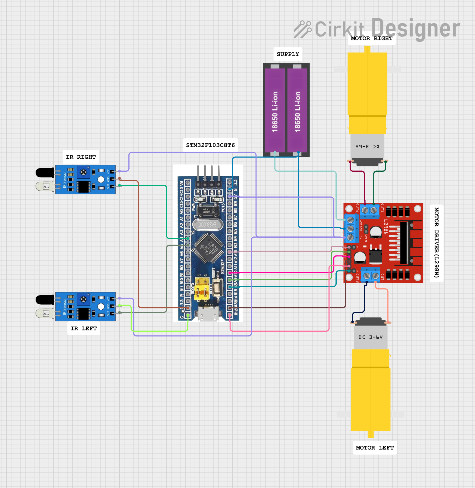
This circuit is a motor control system that uses an STM32F103C8T6 microcontroller to control two DC motors via an L298N motor driver. The system also includes two IR sensors for obstacle detection, powered by a 18650 Li-ion battery pack.
Battery-Powered Dual DC Motor Control System with IR Sensors
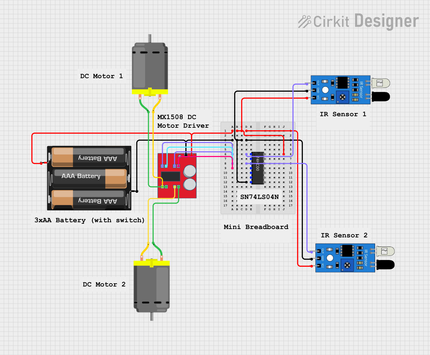
This circuit is a dual-motor control system powered by a 3xAA battery pack, utilizing two IR sensors and a 74HC00 NAND gate to control an MX1508 DC motor driver. The IR sensors provide input signals to the NAND gate, which then drives the motor driver to control the operation of two DC motors.
STM32H7 Controlled Brushless Motors with AS5048 Encoders and CAN Bus Communication
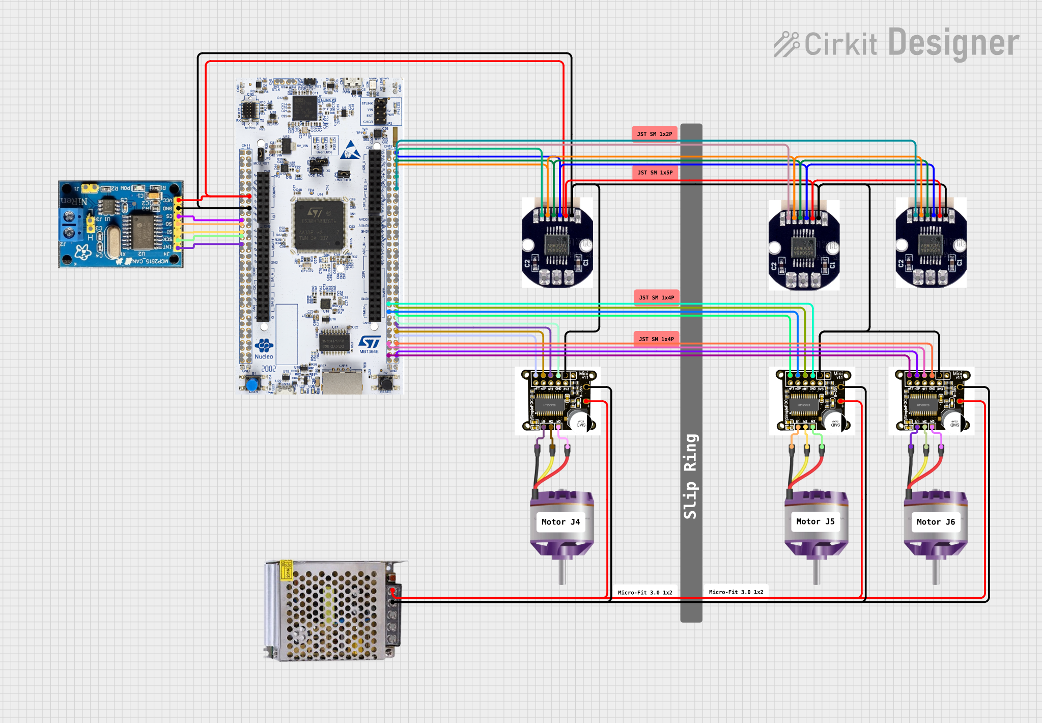
This is a motor control system designed to operate and manage multiple brushless motors with feedback from magnetic encoders. It uses a STM32H7 microcontroller for control logic, SimpleFOCMini drivers for motor control, and a CAN BUS for communication, all powered by a 12V DC supply.
Explore Projects Built with AMR SDD motor controller
Battery-Powered RC Car with Massive RC MDEx and MDD10A Motor Driver
This circuit is a remote-controlled motor driver system powered by a LiPo battery. It uses a Massive RC MDEx microcontroller to control an MDD10A dual motor driver, which in turn drives two GM25 DC motors. The R6FG receiver receives remote control signals to manage the motor directions and speeds.
Battery-Powered Robotic Vehicle with STM32 and L298N Motor Driver
This circuit is a motor control system that uses an STM32F103C8T6 microcontroller to control two DC motors via an L298N motor driver. The system also includes two IR sensors for obstacle detection, powered by a 18650 Li-ion battery pack.
Battery-Powered Dual DC Motor Control System with IR Sensors
This circuit is a dual-motor control system powered by a 3xAA battery pack, utilizing two IR sensors and a 74HC00 NAND gate to control an MX1508 DC motor driver. The IR sensors provide input signals to the NAND gate, which then drives the motor driver to control the operation of two DC motors.
STM32H7 Controlled Brushless Motors with AS5048 Encoders and CAN Bus Communication
This is a motor control system designed to operate and manage multiple brushless motors with feedback from magnetic encoders. It uses a STM32H7 microcontroller for control logic, SimpleFOCMini drivers for motor control, and a CAN BUS for communication, all powered by a 12V DC supply.
Technical Specifications
Key Technical Details
| Parameter | Value |
|---|---|
| Manufacturer | Bizbot Technology |
| Part ID | SDD motor controller |
| Input Voltage | 6V - 24V DC |
| Output Current | 2A continuous, 3A peak |
| Control Signal | PWM (Pulse Width Modulation) |
| Operating Temperature | -20°C to 85°C |
| Dimensions | 50mm x 30mm x 15mm |
Pin Configuration and Descriptions
| Pin Number | Pin Name | Description |
|---|---|---|
| 1 | VCC | Power supply input (6V - 24V DC) |
| 2 | GND | Ground |
| 3 | IN1 | Control signal input 1 (PWM) |
| 4 | IN2 | Control signal input 2 (PWM) |
| 5 | OUT1 | Motor output 1 |
| 6 | OUT2 | Motor output 2 |
| 7 | EN | Enable pin (active high) |
| 8 | FG | Feedback signal (optional, for speed monitoring) |
Usage Instructions
How to Use the Component in a Circuit
- Power Supply Connection: Connect the VCC pin to a DC power supply (6V - 24V) and the GND pin to the ground of the power supply.
- Motor Connection: Connect the motor terminals to the OUT1 and OUT2 pins.
- Control Signal Connection: Connect the PWM control signals to the IN1 and IN2 pins. These signals will control the speed and direction of the motor.
- Enable Pin: Connect the EN pin to a high logic level (e.g., 5V) to enable the motor controller.
- Feedback Signal (Optional): If speed monitoring is required, connect the FG pin to a microcontroller or monitoring device.
Important Considerations and Best Practices
- Ensure that the power supply voltage is within the specified range (6V - 24V DC).
- Use appropriate heat sinks or cooling mechanisms if the motor controller operates at high currents for extended periods.
- Avoid reversing the polarity of the power supply connections to prevent damage to the motor controller.
- Use proper decoupling capacitors near the power supply pins to minimize noise and voltage spikes.
Example Code for Arduino UNO
Below is an example code to control the AMR SDD Motor Controller using an Arduino UNO:
// Define pin connections
const int EN_PIN = 7;  // Enable pin
const int IN1_PIN = 9; // Control signal input 1 (PWM)
const int IN2_PIN = 10; // Control signal input 2 (PWM)

void setup() {
  // Set pin modes
  pinMode(EN_PIN, OUTPUT);
  pinMode(IN1_PIN, OUTPUT);
  pinMode(IN2_PIN, OUTPUT);

  // Enable the motor controller
  digitalWrite(EN_PIN, HIGH);
}

void loop() {
  // Set motor speed and direction
  analogWrite(IN1_PIN, 128); // Set speed (0-255)
  analogWrite(IN2_PIN, 0);   // Set direction

  delay(2000); // Run motor for 2 seconds

  // Change motor direction
  analogWrite(IN1_PIN, 0);
  analogWrite(IN2_PIN, 128);

  delay(2000); // Run motor for 2 seconds
}
Troubleshooting and FAQs
Common Issues Users Might Face
Motor Not Running:
- Solution: Check the power supply connections and ensure the EN pin is set to a high logic level.
Motor Running in Wrong Direction:
- Solution: Verify the PWM signals on IN1 and IN2 pins. Swap the signals if necessary.
Overheating:
- Solution: Ensure proper cooling and heat dissipation. Check for excessive current draw.
No Feedback Signal:
- Solution: Ensure the FG pin is correctly connected and the monitoring device is functioning.
Solutions and Tips for Troubleshooting
- Check Connections: Ensure all connections are secure and correctly oriented.
- Measure Voltages: Use a multimeter to measure voltages at various points in the circuit to identify issues.
- Use Proper Code: Ensure the control code is correctly written and uploaded to the microcontroller.
- Consult Datasheet: Refer to the manufacturer's datasheet for detailed information and specifications.
By following this documentation, users can effectively utilize the AMR SDD Motor Controller in their projects, ensuring reliable and efficient motor control.