The TCRT5000, manufactured by TOI, is an infrared (IR) sensor module that integrates an IR emitter and a phototransistor in a single package. This component is widely used for object detection and proximity sensing due to its ability to detect reflected IR light from nearby objects. Its compact design and reliable performance make it suitable for a variety of applications.
Explore Projects Built with TCRT5000
Use Cirkit Designer to design, explore, and prototype these projects online. Some projects support real-time simulation. Click "Open Project" to start designing instantly!
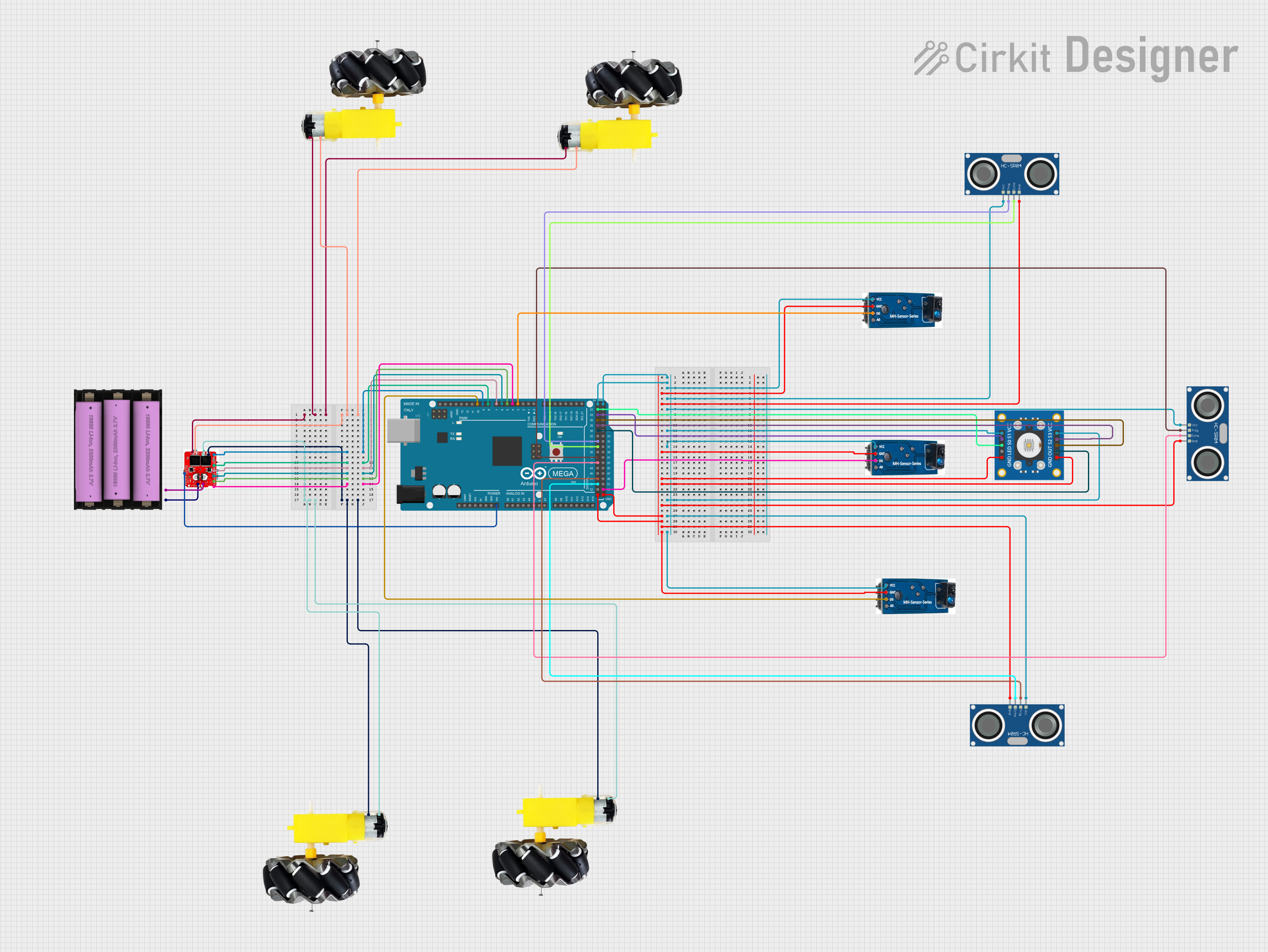
This circuit is a robotic system controlled by an Arduino Mega 2560, which interfaces with multiple sensors including TCRT-5000 IR sensors, HC-SR04 ultrasonic sensors, and a TCS3200 color sensor. The Arduino also controls a motor driver to operate four motors and wheels, powered by a 7V battery, enabling the robot to navigate and interact with its environment.
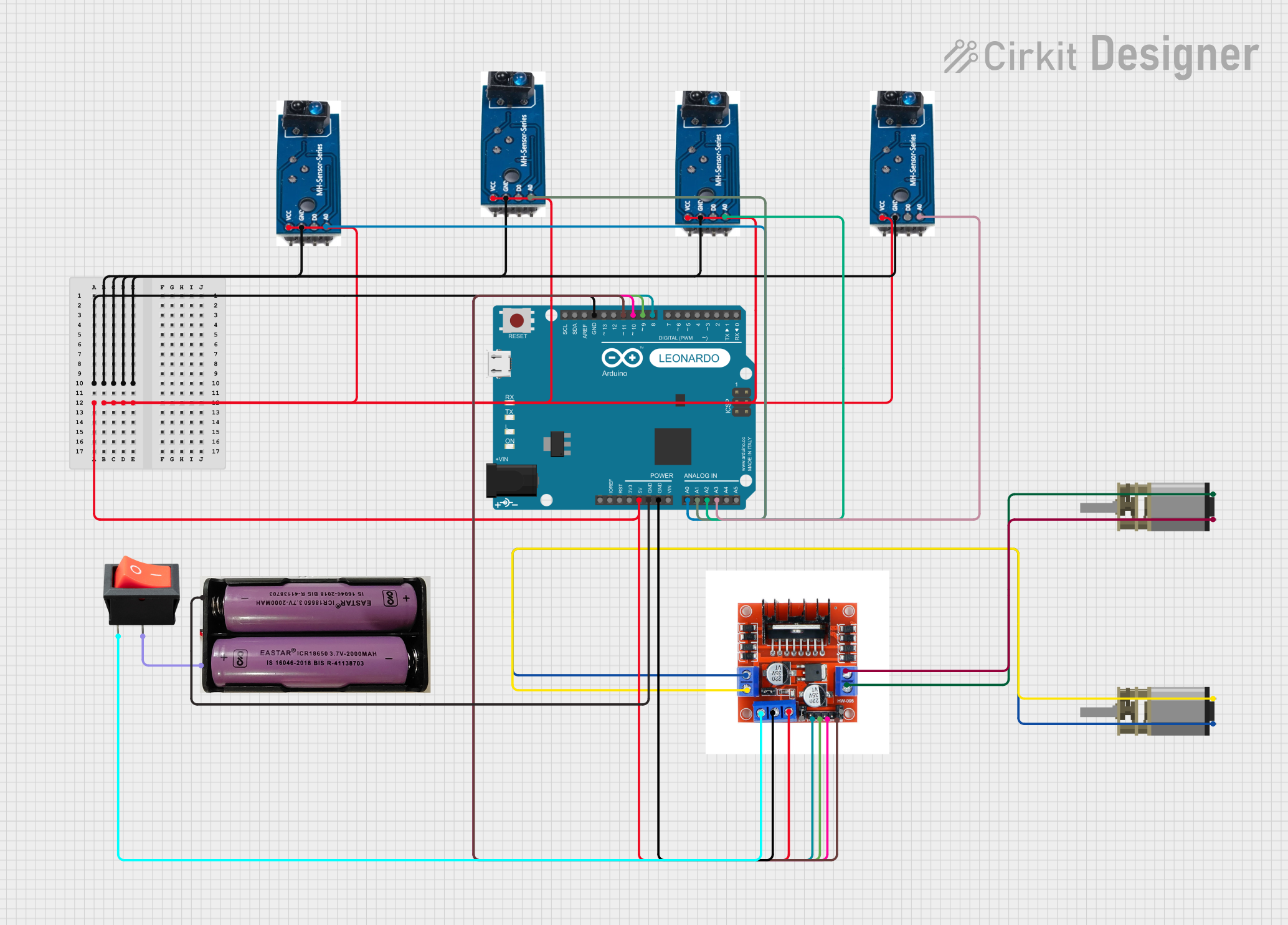
This circuit is a line-following robot that uses four TCRT-5000 IR sensors to detect the path and an Arduino Leonardo to process the sensor data. The Arduino controls two DC motors via an L298N motor driver module, powered by a 7.4V battery and a rocker switch for power control.
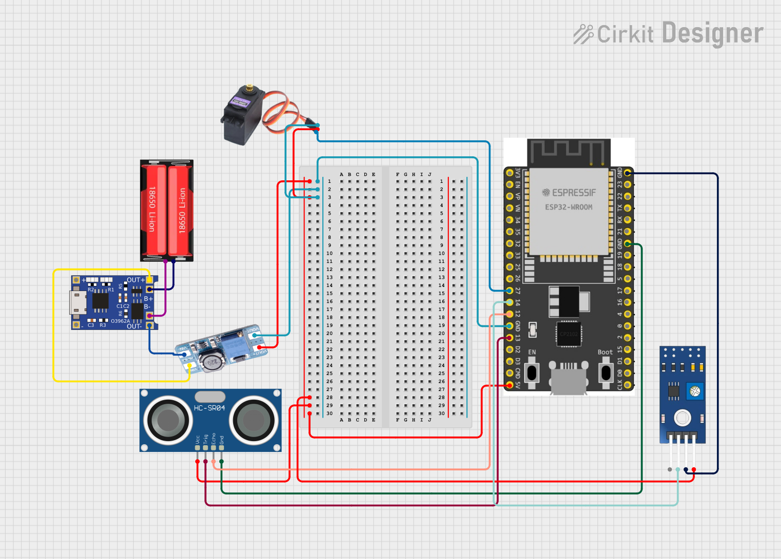
This circuit features a 18650 Li-Ion battery connected to a TP4056 charging module, which in turn is connected to an MT3608 boost converter to step up the voltage. The output of the MT3608 powers an ESP32 microcontroller, a TCRT 5000 IR sensor, an HC-SR04 ultrasonic sensor, and an MG996R servo motor. The ESP32 is configured to control the servo motor via GPIO 27 and to receive input signals from the IR sensor and ultrasonic sensor through GPIO 14 and GPIO 13, respectively.
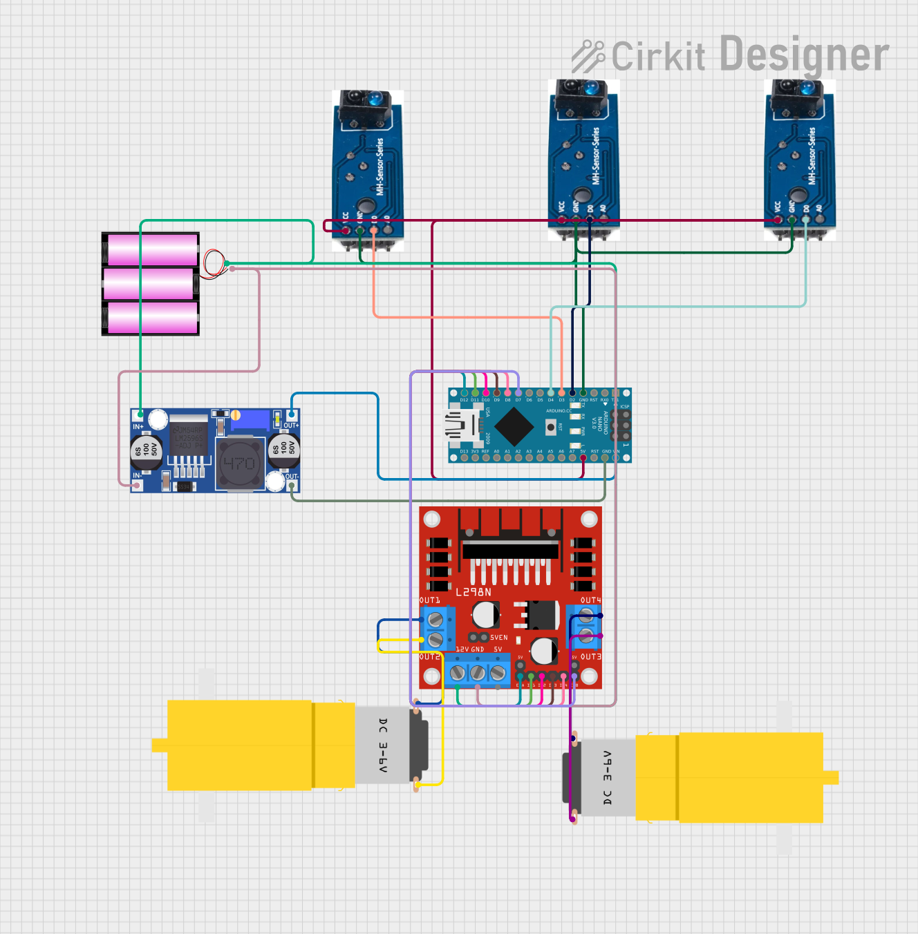
This circuit is a robotic system controlled by an Arduino Nano, which interfaces with three TCRT-5000 IR sensors for obstacle detection and an L298N motor driver to control two DC motors. The system is powered by a 12V battery, regulated by a buck converter to supply the necessary voltage to the Arduino and sensors.
The TCRT5000 is designed for efficient and accurate IR sensing. Below are its key technical details:
Parameter
Value
Operating Voltage
4.5V to 5.5V
Forward Current (IR LED)
60 mA (max)
Collector Current
1 mA (typical)
Peak Wavelength (IR LED)
950 nm
Detection Range
2 mm to 15 mm (optimal: 2-10 mm)
Operating Temperature
-25°C to +85°C
Package Type
Through-hole
Pin Configuration and Descriptions
The TCRT5000 has four pins, as described in the table below:
Pin Number
Name
Description
1
Emitter (A)
Anode of the IR LED. Connect to a current-limiting resistor and then to VCC.
2
Emitter (K)
Cathode of the IR LED. Connect to ground.
3
Collector (C)
Collector of the phototransistor. Outputs a signal based on reflected IR light.
4
Emitter (E)
Emitter of the phototransistor. Connect to ground.
Usage Instructions
The TCRT5000 is straightforward to use in circuits for object detection and proximity sensing. Below are the steps and best practices for using this component:
Circuit Connection
IR LED Connection:
Connect the anode (Pin 1) of the IR LED to a current-limiting resistor (typically 220Ω to 330Ω).
Connect the other end of the resistor to the positive supply voltage (VCC).
Connect the cathode (Pin 2) of the IR LED to ground.
Phototransistor Connection:
Connect the collector (Pin 3) of the phototransistor to a pull-up resistor (e.g., 10kΩ) and then to VCC.
Connect the emitter (Pin 4) of the phototransistor to ground.
The voltage at the collector pin will vary based on the amount of reflected IR light.
Example Circuit with Arduino UNO
The TCRT5000 can be easily interfaced with an Arduino UNO for applications like line-following robots. Below is an example circuit and code:
Circuit Diagram
Connect Pin 1 (IR LED anode) to a 220Ω resistor, and then to the Arduino's 5V pin.
Connect Pin 2 (IR LED cathode) to the Arduino's GND pin.
Connect Pin 3 (phototransistor collector) to a 10kΩ resistor, and then to the Arduino's 5V pin.
Connect Pin 4 (phototransistor emitter) to the Arduino's GND pin.
Connect Pin 3 (phototransistor collector) to an Arduino digital input pin (e.g., D2).
Arduino Code
// TCRT5000 Example Code for Object Detection
// Connect the phototransistor's collector to Arduino pin D2

const int sensorPin = 2; // Digital pin connected to the TCRT5000 output
int sensorValue = 0;     // Variable to store the sensor reading

void setup() {
  pinMode(sensorPin, INPUT); // Set the sensor pin as input
  Serial.begin(9600);        // Initialize serial communication
}

void loop() {
  sensorValue = digitalRead(sensorPin); // Read the sensor output
  if (sensorValue == LOW) {
    // Object detected (IR light reflected back to the sensor)
    Serial.println("Object detected!");
  } else {
    // No object detected
    Serial.println("No object detected.");
  }
  delay(500); // Wait for 500ms before the next reading
}
Best Practices
Optimal Distance: Ensure the object is within the optimal detection range (2-10 mm) for accurate readings.
Ambient Light: Minimize ambient light interference by shielding the sensor or using it in controlled lighting conditions.
Current Limiting: Always use a resistor with the IR LED to prevent damage due to excessive current.
Pull-up Resistor: Use a pull-up resistor with the phototransistor to ensure stable output signals.
Troubleshooting and FAQs
Common Issues and Solutions
No Detection Output:
Cause: Incorrect wiring or insufficient current to the IR LED.
Solution: Verify the connections and ensure the IR LED has a proper current-limiting resistor.
False Positives:
Cause: Ambient IR light interference.
Solution: Use the sensor in a controlled environment or add shielding to block ambient light.
Weak Signal:
Cause: Object is outside the optimal detection range.
Solution: Adjust the distance between the sensor and the object to fall within 2-10 mm.
Overheating:
Cause: Excessive current through the IR LED.
Solution: Use a resistor with an appropriate value (e.g., 220Ω to 330Ω).
FAQs
Q1: Can the TCRT5000 detect transparent objects?
A1: The TCRT5000 is not effective at detecting transparent objects, as they do not reflect sufficient IR light.
Q2: What is the maximum detection range of the TCRT5000?
A2: The maximum detection range is approximately 15 mm, but optimal performance is achieved within 2-10 mm.
Q3: Can the TCRT5000 be used outdoors?
A3: While it can be used outdoors, ambient sunlight may interfere with its performance. Use shielding or filters to reduce interference.
Q4: How do I increase the detection range?
A4: Increasing the IR LED current (within safe limits) or using reflective surfaces can improve the detection range, but it is recommended to stay within the specified range for reliable operation.


 Open Project in Cirkit Designer