
How to Use Adafruit 2.2in PiTFT HAT: Examples, Pinouts, and Specs
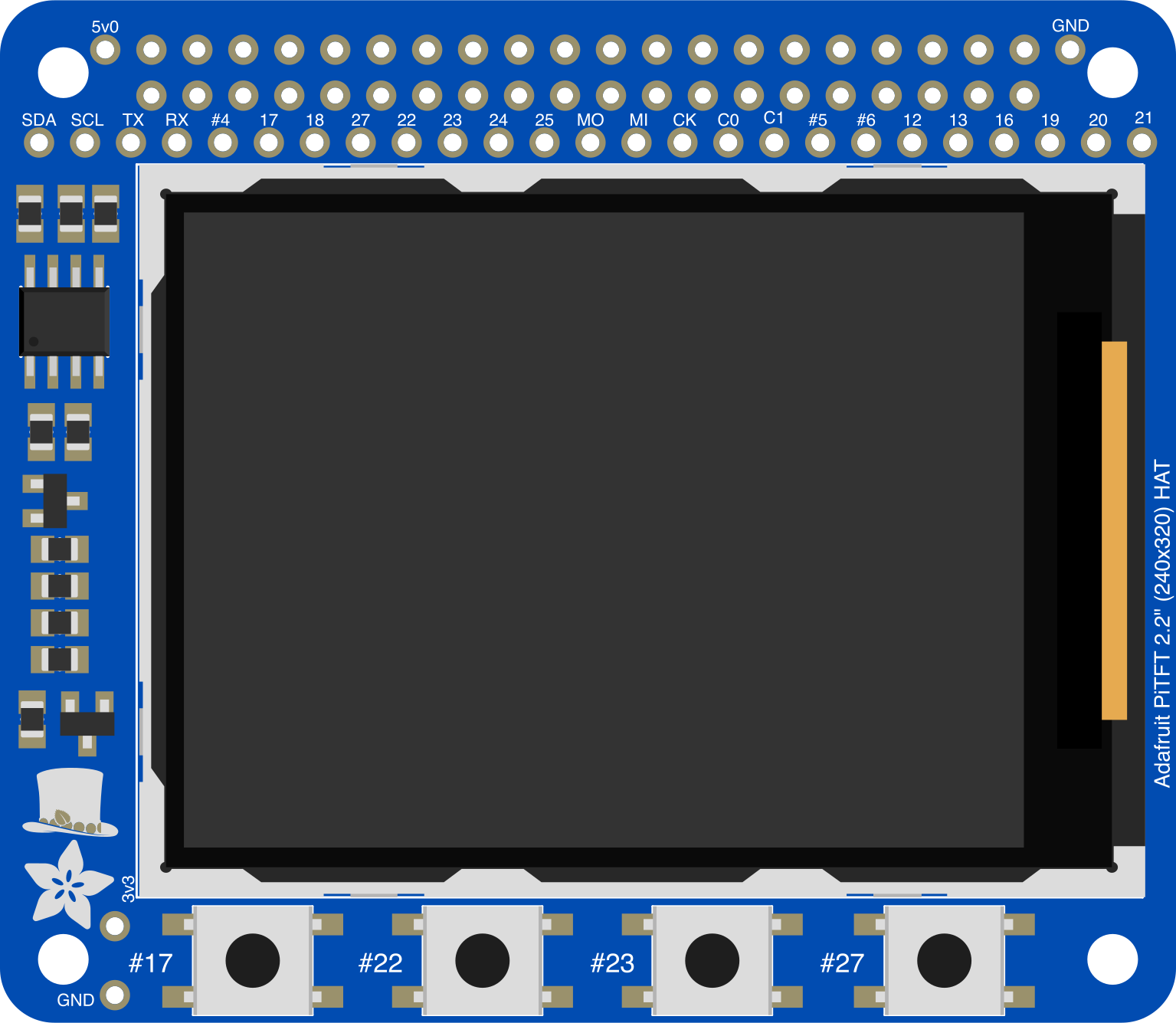
 Design with Adafruit 2.2in PiTFT HAT in Cirkit Designer
Introduction
The Adafruit 2.2in PiTFT HAT (Part ID: 2315) is a compact touchscreen display designed specifically for Raspberry Pi boards. It features a 2.2-inch diagonal screen with a resolution of 320x240 pixels (QVGA), making it ideal for creating portable projects, graphical user interfaces, and interactive displays. The PiTFT HAT integrates seamlessly with Raspberry Pi GPIO pins and includes a resistive touchscreen for user input.
Explore Projects Built with Adafruit 2.2in PiTFT HAT
 Open Project in Cirkit Designer
 Open Project in Cirkit Designer
 Open Project in Cirkit Designer
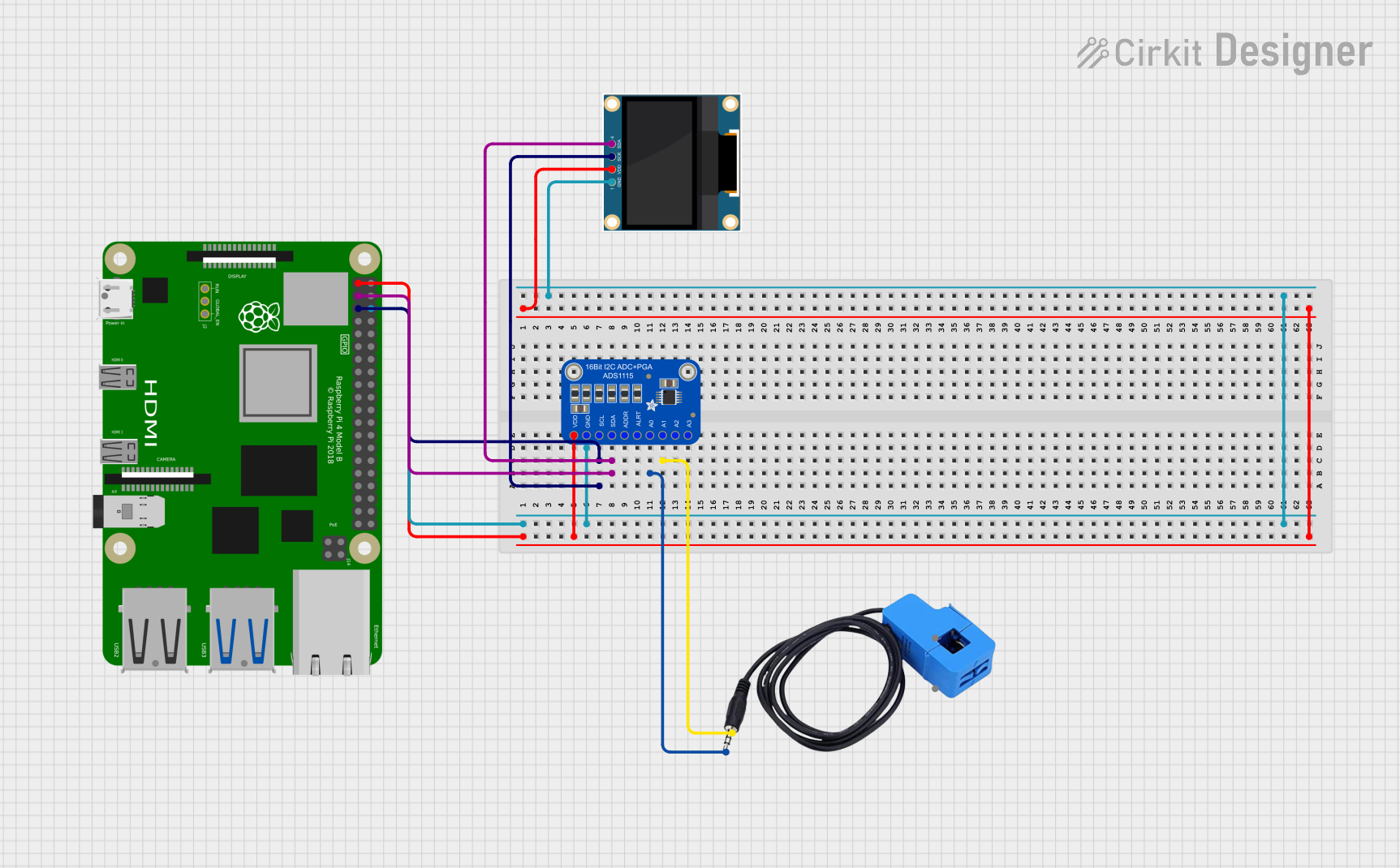 Open Project in Cirkit Designer
Explore Projects Built with Adafruit 2.2in PiTFT HAT
Open Project in Cirkit DesignerOpen Project in Cirkit DesignerOpen Project in Cirkit DesignerOpen Project in Cirkit DesignerCommon Applications and Use Cases
- Portable Raspberry Pi projects
- Custom graphical user interfaces
- IoT dashboards and control panels
- Educational tools and interactive displays
- Compact gaming consoles
Technical Specifications
Below are the key technical details of the Adafruit 2.2in PiTFT HAT:
| Specification | Details |
|---|---|
| Screen Size | 2.2 inches (diagonal) |
| Resolution | 320x240 pixels (QVGA) |
| Touchscreen Type | Resistive touchscreen |
| Interface | SPI (Serial Peripheral Interface) |
| Backlight Control | GPIO-controlled |
| Power Supply Voltage | 3.3V (via Raspberry Pi GPIO) |
| Dimensions | 65mm x 56mm x 6mm |
| Weight | ~20g |
Pin Configuration and Descriptions
The PiTFT HAT connects directly to the Raspberry Pi GPIO header. Below is the pin configuration:
| Pin | GPIO Pin | Function |
|---|---|---|
| 1 | 3.3V | Power supply |
| 6 | GND | Ground |
| 19 | GPIO10 (MOSI) | SPI data input |
| 21 | GPIO9 (MISO) | SPI data output |
| 23 | GPIO11 (SCLK) | SPI clock |
| 24 | GPIO8 (CE0) | SPI chip select |
| 18 | GPIO24 | Backlight control |
| 22 | GPIO25 | Touchscreen interrupt |
Usage Instructions
How to Use the Component in a Circuit
Hardware Setup:
- Align the Adafruit 2.2in PiTFT HAT with the Raspberry Pi GPIO header.
- Gently press the HAT onto the GPIO pins to ensure a secure connection.
- Power on the Raspberry Pi.
Software Setup:
- Install the required libraries and drivers for the PiTFT HAT:
sudo apt-get update sudo apt-get install -y python3-pip sudo pip3 install adafruit-blinka adafruit-circuitpython-ili9341 - Configure the Raspberry Pi to use the SPI interface:
sudo raspi-config- Navigate to Interfacing Options > SPI and enable it.
- Reboot the Raspberry Pi.
- Install the required libraries and drivers for the PiTFT HAT:
Display Test:
- Run the following Python script to test the display:
import board
import digitalio
from adafruit_ili9341 import ILI9341
import displayio

# Initialize SPI interface
spi = board.SPI()  # Uses GPIO10 (MOSI), GPIO11 (SCLK), GPIO8 (CE0)
tft_cs = digitalio.DigitalInOut(board.CE0)  # Chip select
tft_dc = digitalio.DigitalInOut(board.D25)  # Data/command
tft_reset = digitalio.DigitalInOut(board.D24)  # Reset

# Create the display object
display_bus = displayio.FourWire(spi, command=tft_dc, chip_select=tft_cs,
                                 reset=tft_reset)
display = ILI9341(display_bus, width=320, height=240)

# Fill the screen with a solid color
splash = displayio.Group()
display.show(splash)
color_bitmap = displayio.Bitmap(320, 240, 1)
color_palette = displayio.Palette(1)
color_palette[0] = 0xFF0000  # Red
bg_sprite = displayio.TileGrid(color_bitmap, pixel_shader=color_palette,
                               x=0, y=0)
splash.append(bg_sprite)

while True:
    pass  # Keeps the display running
- Run the following Python script to test the display:
Important Considerations and Best Practices
- Ensure the Raspberry Pi is powered off before attaching or detaching the PiTFT HAT.
- Use a stable 5V power supply for the Raspberry Pi to avoid display flickering.
- Avoid applying excessive pressure to the resistive touchscreen to prevent damage.
- For optimal performance, use the latest Raspberry Pi OS and keep all libraries updated.
Troubleshooting and FAQs
Common Issues and Solutions
The display is not turning on:
- Ensure the PiTFT HAT is securely connected to the Raspberry Pi GPIO header.
- Verify that the SPI interface is enabled in the Raspberry Pi configuration.
- Check the power supply voltage and ensure it meets the requirements.
Touchscreen is unresponsive:
- Confirm that the touchscreen interrupt pin (GPIO25) is properly configured.
- Reinstall the touchscreen drivers using Adafruit's setup guide.
Display shows a blank screen:
- Verify the Python script is correctly configured for the ILI9341 driver.
- Check the SPI connections and ensure no pins are loose or misaligned.
Backlight is not working:
- Ensure GPIO24 is configured for backlight control.
- Test the backlight functionality using a simple GPIO toggle script.
FAQs
Q: Can I use this display with Arduino boards?
A: The Adafruit 2.2in PiTFT HAT is designed for Raspberry Pi and uses the GPIO header. While it may be possible to adapt it for Arduino using SPI, it is not officially supported.
Q: Does the PiTFT HAT support multitouch?
A: No, the resistive touchscreen supports single-touch input only.
Q: Can I use this display in portrait mode?
A: Yes, the display orientation can be configured in software to support portrait or landscape modes.
Q: Is the display sunlight-readable?
A: The display is not optimized for outdoor use and may be difficult to read in direct sunlight.