
How to Use L298: Examples, Pinouts, and Specs

 Design with L298 in Cirkit Designer
Introduction
The L298 is a dual H-bridge motor driver IC designed to control the direction and speed of DC motors and stepper motors. It is capable of driving two motors simultaneously, making it a versatile choice for robotics, automation, and other motor control applications. With its ability to handle high current loads, the L298 is widely used in projects requiring precise motor control, such as robotic arms, conveyor belts, and automated vehicles.
Explore Projects Built with L298
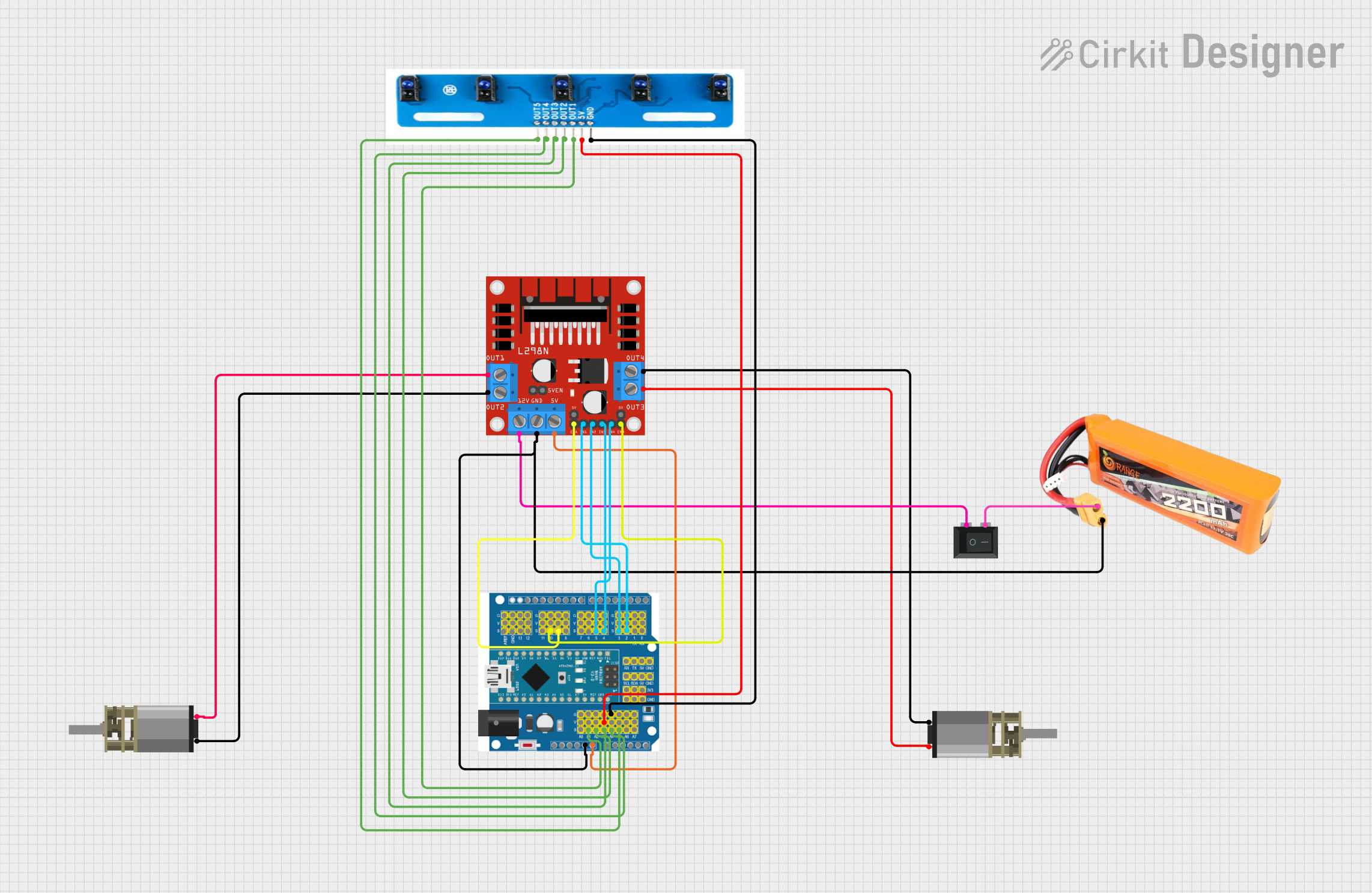 Open Project in Cirkit Designer
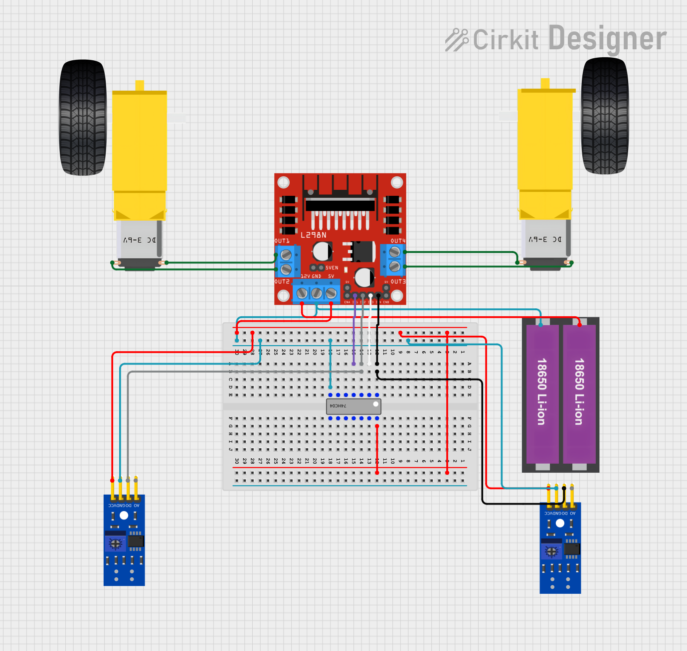 Open Project in Cirkit Designer
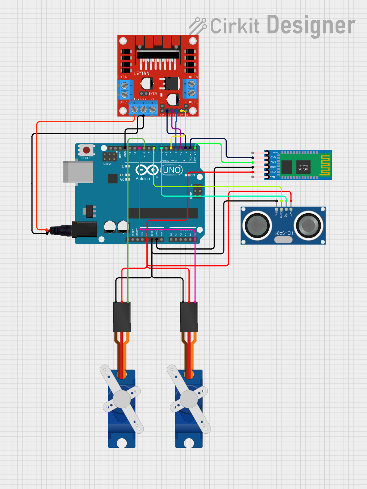 Open Project in Cirkit Designer
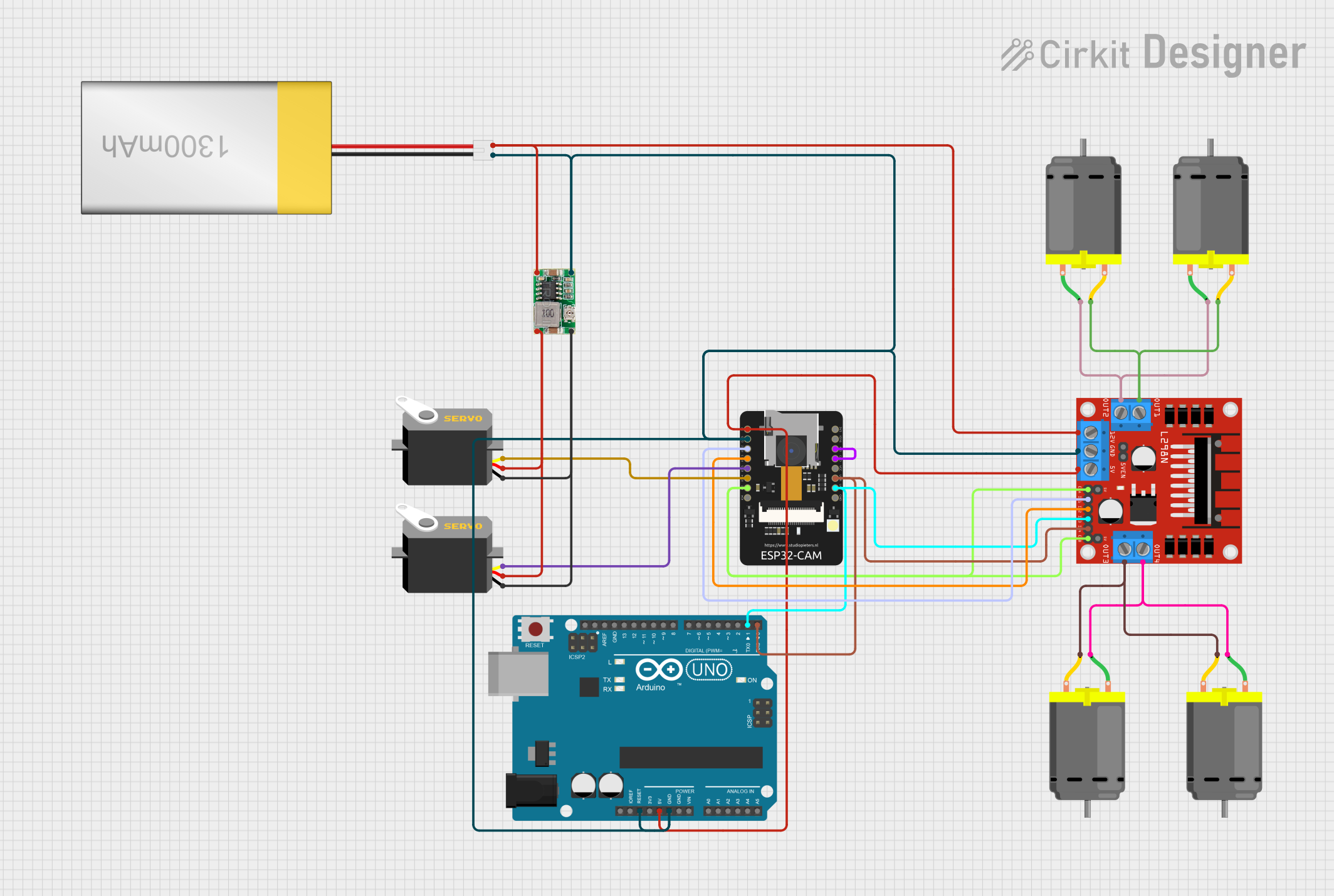 Open Project in Cirkit Designer
Explore Projects Built with L298
Open Project in Cirkit DesignerOpen Project in Cirkit DesignerOpen Project in Cirkit DesignerOpen Project in Cirkit DesignerCommon Applications:
- Robotics (e.g., controlling wheels or robotic arms)
- Automation systems
- CNC machines
- Stepper motor control
- DIY motorized projects
Technical Specifications
Below are the key technical details of the L298 motor driver IC:
| Parameter | Value |
|---|---|
| Operating Voltage | 4.5V to 46V |
| Maximum Output Current | 2A per channel (continuous) |
| Peak Output Current | 3A per channel (non-repetitive) |
| Logic Voltage | 5V |
| Power Dissipation | 25W (with proper heat sinking) |
| Control Logic Levels | Low: 0V, High: 5V |
| Operating Temperature | -25°C to +130°C |
| Motor Types Supported | DC motors, stepper motors |
Pin Configuration and Descriptions
The L298 IC comes in a 15-pin Multiwatt package. Below is the pin configuration:
| Pin Number | Pin Name | Description |
|---|---|---|
| 1 | Current Sense A | Connect to ground via a resistor to monitor current for Motor A. |
| 2 | Output 1 | Output pin for Motor A (connect to one terminal of the motor). |
| 3 | Output 2 | Output pin for Motor A (connect to the other terminal of the motor). |
| 4 | VSS | Logic supply voltage (typically 5V). |
| 5 | Input 1 | Logic input to control Motor A (High/Low). |
| 6 | Input 2 | Logic input to control Motor A (High/Low). |
| 7 | Enable A | Enable pin for Motor A (High to enable, Low to disable). |
| 8 | Ground | Common ground for logic and motor power. |
| 9 | Ground | Common ground for logic and motor power. |
| 10 | Enable B | Enable pin for Motor B (High to enable, Low to disable). |
| 11 | Input 3 | Logic input to control Motor B (High/Low). |
| 12 | Input 4 | Logic input to control Motor B (High/Low). |
| 13 | VSS | Logic supply voltage (typically 5V). |
| 14 | Output 3 | Output pin for Motor B (connect to one terminal of the motor). |
| 15 | Output 4 | Output pin for Motor B (connect to the other terminal of the motor). |
Usage Instructions
How to Use the L298 in a Circuit
Power Connections:
- Connect the motor power supply (4.5V to 46V) to the
VSSpin. - Connect the logic power supply (5V) to the
VSSpin for the control logic. - Connect the ground pins (8 and 9) to the common ground of the circuit.
- Connect the motor power supply (4.5V to 46V) to the
Motor Connections:
- For Motor A, connect its terminals to
Output 1andOutput 2. - For Motor B, connect its terminals to
Output 3andOutput 4.
- For Motor A, connect its terminals to
Control Logic:
- Use the
Inputpins (1, 2 for Motor A; 3, 4 for Motor B) to control the direction of the motors. - Use the
Enablepins (7 for Motor A; 10 for Motor B) to enable or disable the motors.
- Use the
Current Sensing (Optional):
- Connect a resistor between the
Current Sensepins (1 for Motor A; 15 for Motor B) and ground to monitor the current.
- Connect a resistor between the
Example: Connecting L298 to an Arduino UNO
Below is an example of how to control a DC motor using the L298 and an Arduino UNO:
Circuit Connections:
- Connect
Enable Ato Arduino pin 9. - Connect
Input 1to Arduino pin 8. - Connect
Input 2to Arduino pin 7. - Connect the motor terminals to
Output 1andOutput 2. - Connect the motor power supply to
VSSand ground.
Arduino Code:
// Define pins for L298 connections
const int enableA = 9;  // Enable pin for Motor A
const int input1 = 8;   // Input 1 for Motor A
const int input2 = 7;   // Input 2 for Motor A

void setup() {
  // Set pin modes
  pinMode(enableA, OUTPUT);
  pinMode(input1, OUTPUT);
  pinMode(input2, OUTPUT);

  // Initialize motor in stopped state
  digitalWrite(enableA, LOW);  // Disable motor
  digitalWrite(input1, LOW);   // Set direction to LOW
  digitalWrite(input2, LOW);   // Set direction to LOW
}

void loop() {
  // Example: Rotate motor forward
  digitalWrite(enableA, HIGH);  // Enable motor
  digitalWrite(input1, HIGH);   // Set direction forward
  digitalWrite(input2, LOW);    // Set direction forward
  delay(2000);                  // Run motor for 2 seconds

  // Example: Rotate motor backward
  digitalWrite(input1, LOW);    // Set direction backward
  digitalWrite(input2, HIGH);   // Set direction backward
  delay(2000);                  // Run motor for 2 seconds

  // Stop motor
  digitalWrite(enableA, LOW);   // Disable motor
  delay(2000);                  // Wait for 2 seconds
}
Important Considerations:
- Use a heat sink with the L298 to prevent overheating during high current operation.
- Ensure the motor power supply voltage matches the motor's specifications.
- Avoid exceeding the maximum current rating (2A per channel) to prevent damage.
Troubleshooting and FAQs
Common Issues and Solutions:
Motor Not Running:
- Check if the
Enablepin is set to HIGH. - Verify the power supply connections and ensure sufficient voltage is provided.
- Check if the
Overheating:
- Attach a heat sink to the L298 IC.
- Reduce the motor load or use a motor with lower current requirements.
Erratic Motor Behavior:
- Ensure proper grounding of the circuit.
- Check for loose connections or damaged wires.
Arduino Not Controlling the Motor:
- Verify the Arduino pin connections to the L298.
- Ensure the logic voltage (5V) is supplied to the L298.
FAQs:
Q: Can the L298 drive stepper motors?
A: Yes, the L298 can drive stepper motors by controlling the sequence of inputs to the H-bridges.
Q: What is the purpose of the Current Sense pins?
A: The Current Sense pins allow you to monitor the current flowing through each motor channel by connecting a resistor and measuring the voltage drop.
Q: Can I use the L298 without a heat sink?
A: While it is possible for low-current applications, a heat sink is recommended for high-current loads to prevent overheating.
Q: What is the maximum voltage the L298 can handle?
A: The L298 can handle up to 46V for the motor power supply.