Cirkit Designer Logo
Cirkit Designer
Your all-in-one circuit design IDE
Home / 
Component Documentation

How to Use lm2596: Examples, Pinouts, and Specs

Image of lm2596
Cirkit Designer LogoDesign with lm2596 in Cirkit Designer

Introduction

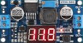
The LM2596 is a step-down (buck) voltage regulator designed to efficiently convert a higher input voltage into a stable, regulated output voltage. It is capable of delivering up to 3A of output current, making it ideal for powering a wide range of electronic devices. With its wide input voltage range (typically 4.5V to 40V), the LM2596 is a versatile component for power management in various applications.

Explore Projects Built with lm2596

Use Cirkit Designer to design, explore, and prototype these projects online. Some projects support real-time simulation. Click "Open Project" to start designing instantly!
Voltage Regulation System with MT3608 Boost and LM2596 Buck Converters
Image of solar system router ups: A project utilizing lm2596 in a practical application
This circuit consists of two MT3608 boost converters and an LM2596 step-down module, each connected to separate 12V power supplies. The MT3608 modules are configured to step up the voltage from their respective power supplies, while the LM2596 module steps down the voltage from a 12V battery. Diodes are used to ensure correct current flow direction, potentially for protection or isolation between different parts of the circuit.
Cirkit Designer LogoOpen Project in Cirkit Designer
Arduino Nano Based GPS Tracker with GSM Communication and Accelerometer
Image of Circuit Aayush: A project utilizing lm2596 in a practical application
This circuit is designed for communication and location tracking purposes. It features an Arduino Nano interfaced with a SIM800L GSM module for cellular connectivity, a GPS NEO 6M module for obtaining geographical coordinates, and an AITrip ADXL335 GY-61 accelerometer for motion sensing. The LM2596 Step Down Module is used to regulate the power supply to the components.
Cirkit Designer LogoOpen Project in Cirkit Designer
Arduino GSM Security System with Motion Detection and Light Sensing
Image of Smart Home Security: A project utilizing lm2596 in a practical application
This circuit is designed to interface an Arduino UNO with a SIM800L GSM module, PIR sensor, photocell, buzzer, and multiple LEDs. It is likely intended for environmental monitoring and alerting, with the capability to communicate over GSM for remote notifications. The LM2596 module provides voltage regulation for the GSM module.
Cirkit Designer LogoOpen Project in Cirkit Designer
Cellular-Enabled IoT Device with Real-Time Clock and Power Management
Image of LRCM PHASE 2 BASIC: A project utilizing lm2596 in a practical application
This circuit features a LilyGo-SIM7000G module for cellular communication and GPS functionality, interfaced with an RTC DS3231 for real-time clock capabilities. It includes voltage sensing through two voltage sensor modules, and uses an 8-channel opto-coupler for isolating different parts of the circuit. Power management is handled by a buck converter connected to a DC power source and batteries, with a fuse for protection and a rocker switch for on/off control. Additionally, there's an LED for indication purposes.
Cirkit Designer LogoOpen Project in Cirkit Designer

Explore Projects Built with lm2596

Use Cirkit Designer to design, explore, and prototype these projects online. Some projects support real-time simulation. Click "Open Project" to start designing instantly!
Image of solar system router ups: A project utilizing lm2596 in a practical application
Voltage Regulation System with MT3608 Boost and LM2596 Buck Converters
This circuit consists of two MT3608 boost converters and an LM2596 step-down module, each connected to separate 12V power supplies. The MT3608 modules are configured to step up the voltage from their respective power supplies, while the LM2596 module steps down the voltage from a 12V battery. Diodes are used to ensure correct current flow direction, potentially for protection or isolation between different parts of the circuit.
Cirkit Designer LogoOpen Project in Cirkit Designer
Image of Circuit Aayush: A project utilizing lm2596 in a practical application
Arduino Nano Based GPS Tracker with GSM Communication and Accelerometer
This circuit is designed for communication and location tracking purposes. It features an Arduino Nano interfaced with a SIM800L GSM module for cellular connectivity, a GPS NEO 6M module for obtaining geographical coordinates, and an AITrip ADXL335 GY-61 accelerometer for motion sensing. The LM2596 Step Down Module is used to regulate the power supply to the components.
Cirkit Designer LogoOpen Project in Cirkit Designer
Image of Smart Home Security: A project utilizing lm2596 in a practical application
Arduino GSM Security System with Motion Detection and Light Sensing
This circuit is designed to interface an Arduino UNO with a SIM800L GSM module, PIR sensor, photocell, buzzer, and multiple LEDs. It is likely intended for environmental monitoring and alerting, with the capability to communicate over GSM for remote notifications. The LM2596 module provides voltage regulation for the GSM module.
Cirkit Designer LogoOpen Project in Cirkit Designer
Image of LRCM PHASE 2 BASIC: A project utilizing lm2596 in a practical application
Cellular-Enabled IoT Device with Real-Time Clock and Power Management
This circuit features a LilyGo-SIM7000G module for cellular communication and GPS functionality, interfaced with an RTC DS3231 for real-time clock capabilities. It includes voltage sensing through two voltage sensor modules, and uses an 8-channel opto-coupler for isolating different parts of the circuit. Power management is handled by a buck converter connected to a DC power source and batteries, with a fuse for protection and a rocker switch for on/off control. Additionally, there's an LED for indication purposes.
Cirkit Designer LogoOpen Project in Cirkit Designer

Common Applications and Use Cases

  • Power supply circuits for microcontrollers, sensors, and modules
  • Battery-powered devices requiring efficient voltage regulation
  • DC-DC converters in industrial and automotive systems
  • Adjustable voltage regulators for prototyping and testing
  • LED drivers and low-voltage lighting systems

Technical Specifications

The LM2596 is available in both fixed output voltage versions (e.g., 3.3V, 5V, 12V) and an adjustable version. Below are the key technical details:

Key Specifications

  • Input Voltage Range: 4.5V to 40V
  • Output Voltage Range: 1.23V to 37V (adjustable version)
  • Output Current: Up to 3A
  • Efficiency: Up to 90% (depending on input/output conditions)
  • Switching Frequency: 150 kHz (typical)
  • Thermal Shutdown: Yes
  • Overcurrent Protection: Yes
  • Package Type: TO-220 or TO-263 (commonly used)

Pin Configuration and Descriptions

The LM2596 typically comes in a 5-pin TO-220 or TO-263 package. Below is the pinout description:

Pin Number Pin Name Description
1 VIN Input voltage pin. Connect to the unregulated DC input voltage.
2 Output Regulated output voltage pin. Connect to the load.
3 Ground (GND) Ground pin. Connect to the circuit ground.
4 Feedback Feedback pin. Used to set the output voltage (adjustable version only).
5 ON/OFF Enable pin. Pull low to disable the regulator; leave open or pull high to enable.

Usage Instructions

How to Use the LM2596 in a Circuit

  1. Input Voltage: Connect the input voltage (VIN) to the LM2596's VIN pin. Ensure the input voltage is within the specified range (4.5V to 40V).
  2. Output Voltage: For fixed versions, the output voltage is pre-set (e.g., 5V). For the adjustable version:
    • Use a resistor divider network connected to the Feedback pin to set the desired output voltage.
    • The output voltage can be calculated using the formula:
      [ V_{OUT} = V_{REF} \times \left(1 + \frac{R1}{R2}\right) ]
      where ( V_{REF} ) is typically 1.23V.
  3. Capacitors: Add input and output capacitors (e.g., 100µF electrolytic) to stabilize the circuit and reduce noise.
  4. Inductor: Select an appropriate inductor value based on the desired output current and voltage.
  5. Enable Pin: Leave the ON/OFF pin open or pull it high to enable the regulator. Pull it low to disable the output.

Important Considerations and Best Practices

  • Heat Dissipation: The LM2596 can generate heat under high load conditions. Use a heatsink or ensure proper ventilation to prevent overheating.
  • Input Voltage: Ensure the input voltage is at least 3V higher than the desired output voltage for proper regulation.
  • Output Ripple: Use low-ESR capacitors to minimize output voltage ripple.
  • PCB Layout: Keep the input and output capacitor connections as short as possible to reduce noise and improve stability.

Example: Using LM2596 with Arduino UNO

The LM2596 can be used to power an Arduino UNO by stepping down a 12V input to 5V. Below is an example circuit and Arduino code:

Circuit Connections

  • Connect a 12V DC input to the VIN pin of the LM2596.
  • Set the output voltage to 5V using the adjustable version of the LM2596.
  • Connect the 5V output to the Arduino UNO's 5V pin.
  • Connect the GND pin of the LM2596 to the Arduino's GND.

Arduino Code Example

// Example code to blink an LED using Arduino UNO powered by LM2596
// Ensure the LM2596 output is set to 5V before connecting to the Arduino

const int ledPin = 13; // Built-in LED pin on Arduino UNO

void setup() {
  pinMode(ledPin, OUTPUT); // Set LED pin as output
}

void loop() {
  digitalWrite(ledPin, HIGH); // Turn the LED on
  delay(1000);                // Wait for 1 second
  digitalWrite(ledPin, LOW);  // Turn the LED off
  delay(1000);                // Wait for 1 second
}

Troubleshooting and FAQs

Common Issues and Solutions

  1. No Output Voltage:

    • Check if the input voltage is within the specified range.
    • Ensure the ON/OFF pin is not pulled low.
    • Verify the connections and ensure the circuit is properly assembled.
  2. Overheating:

    • Ensure the load current does not exceed 3A.
    • Use a heatsink or improve ventilation around the LM2596.
  3. High Output Ripple:

    • Use low-ESR capacitors on the input and output.
    • Check the inductor value and ensure it is appropriate for the load.
  4. Incorrect Output Voltage:

    • For the adjustable version, verify the resistor divider values.
    • Ensure the Feedback pin is properly connected.

FAQs

  • Can the LM2596 be used with batteries?
    Yes, the LM2596 can step down the voltage from a battery to a lower, regulated voltage. Ensure the battery voltage is within the input range.

  • What is the maximum input voltage for the LM2596?
    The maximum input voltage is 40V. Exceeding this value may damage the component.

  • Can the LM2596 be used for negative voltage regulation?
    No, the LM2596 is designed for positive voltage regulation only.

  • How do I calculate the inductor value?
    Refer to the datasheet for detailed guidelines on selecting the inductor value based on the input/output voltage and load current.

By following this documentation, you can effectively use the LM2596 in your projects and troubleshoot common issues.