How to Use Seeed Studio Temperature Sensor: Examples, Pinouts, and Specs
Introduction
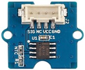
The Seeed Studio Temperature Sensor is an electronic device designed to measure ambient temperature with high accuracy. It is commonly used in a variety of applications such as environmental monitoring, home automation systems, and industrial temperature control. The sensor provides an analog output that can be easily interfaced with microcontrollers like the Arduino UNO.
Explore Projects Built with Seeed Studio Temperature Sensor

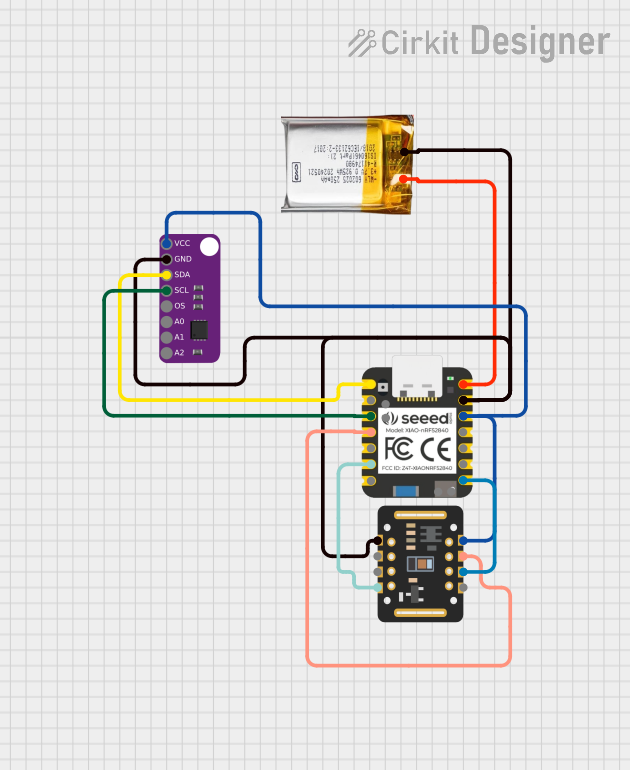
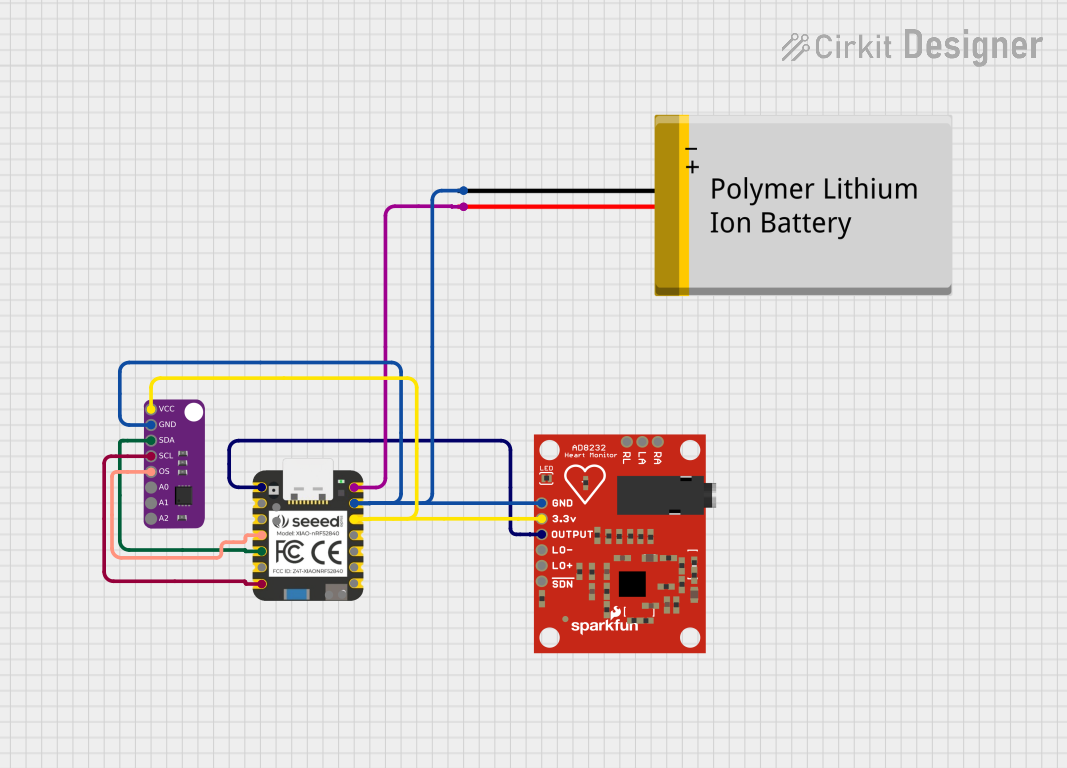
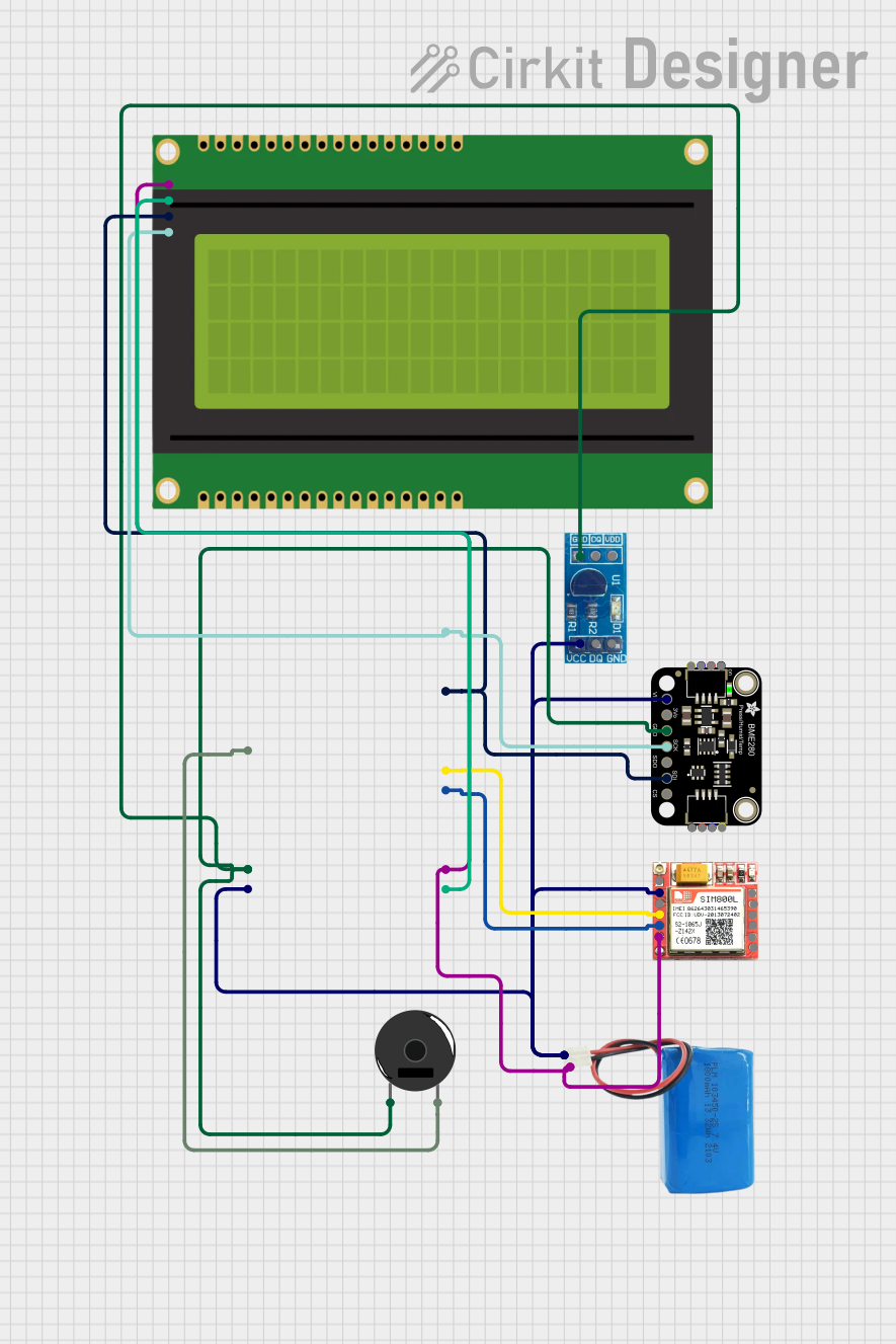
Explore Projects Built with Seeed Studio Temperature Sensor
Technical Specifications
Key Technical Details
- Operating Voltage: 3.3V to 5V
- Measurement Range: -40°C to +125°C
- Accuracy: ±0.5°C
- Output: Analog voltage
- Response Time: < 750 ms
Pin Configuration and Descriptions
| Pin Number | Name | Description |
|---|---|---|
| 1 | VCC | Power supply (3.3V to 5V) |
| 2 | GND | Ground connection |
| 3 | SIG | Analog signal output |
Usage Instructions
Interfacing with Arduino UNO
- Connect the VCC pin of the temperature sensor to the 5V output on the Arduino UNO.
- Connect the GND pin to one of the GND pins on the Arduino UNO.
- Connect the SIG pin to an analog input on the Arduino UNO (e.g., A0).
Sample Arduino Code
// Define the analog pin connected to the temperature sensor
const int tempSensorPin = A0;

void setup() {
  // Initialize serial communication at 9600 bits per second:
  Serial.begin(9600);
}

void loop() {
  // Read the value from the sensor:
  int sensorValue = analogRead(tempSensorPin);
  // Convert the analog reading to voltage (assuming 5V power supply)
  float voltage = sensorValue * (5.0 / 1023.0);
  // Convert the voltage to temperature in Celsius
  float temperature = (voltage - 0.5) * 100.0;

  // Print the temperature to the Serial Monitor
  Serial.print("Temperature: ");
  Serial.print(temperature);
  Serial.println(" C");

  // Delay for a second before reading again
  delay(1000);
}
Important Considerations and Best Practices
- Ensure that the power supply voltage does not exceed the sensor's maximum rating.
- Avoid placing the sensor near heat-generating components to prevent false readings.
- Use shielded cables if the sensor is placed in an environment with high electrical noise.
Troubleshooting and FAQs
Common Issues
- Inaccurate Temperature Readings: Ensure that the sensor is not exposed to sudden temperature changes and is not placed near heat sources.
- No Output Signal: Check the connections and ensure that the sensor is properly powered.
Solutions and Tips
- For more stable readings, average multiple sensor readings.
- Use a pull-down resistor if you encounter floating analog input values.
FAQs
Q: Can I use this sensor with a 3.3V system? A: Yes, the sensor can be powered with 3.3V to 5V.
Q: How can I calibrate the sensor? A: Compare the sensor output with a known temperature reference and adjust the calculation in your code accordingly.
Q: Is the sensor waterproof? A: No, the Seeed Studio Temperature Sensor is not waterproof. Protect it from moisture to ensure proper operation.
Q: How long should I wait between readings? A: The sensor has a response time of less than 750 ms, but for more stable readings, a delay of 1 second between readings is recommended.
For further assistance, please refer to the Seeed Studio community forums or contact technical support.