Cirkit Designer Logo
Cirkit Designer
Your all-in-one circuit design IDE
Home / 
Component Documentation

How to Use Adafruit AS7341: Examples, Pinouts, and Specs

Image of Adafruit AS7341
Cirkit Designer LogoDesign with Adafruit AS7341 in Cirkit Designer

Introduction

The Adafruit AS7341 is a highly versatile spectral sensor capable of measuring light intensity across multiple wavelengths. It features 6 color sensing channels, along with additional near-infrared and clear channels, enabling precise color detection and spectral analysis. This makes the AS7341 an excellent choice for applications such as color matching, environmental monitoring, robotics, and scientific research.

The sensor is compact and communicates via the I2C protocol, making it easy to integrate into microcontroller-based systems like Arduino or Raspberry Pi. Its high sensitivity and advanced features allow for accurate measurements even in low-light conditions.

Explore Projects Built with Adafruit AS7341

Use Cirkit Designer to design, explore, and prototype these projects online. Some projects support real-time simulation. Click "Open Project" to start designing instantly!
Arduino Mega 2560 Multi-Sensor Data Logger with I2C Multiplexer
Image of Gesamt Schaltplan: A project utilizing Adafruit AS7341 in a practical application
This circuit uses an Arduino Mega 2560 to interface with multiple sensors, including an Adafruit ADXL326 accelerometer, a pressure transducer, and two MLX90614 IR temperature sensors connected via an Adafruit TCA9548A I2C multiplexer. The Arduino reads data from these sensors and outputs the values to the Serial Monitor.
Cirkit Designer LogoOpen Project in Cirkit Designer
Arduino Nano Controlled Smart Relay with APDS-9960 Gesture Sensor
Image of contactless smart switch: A project utilizing Adafruit AS7341 in a practical application
This circuit features an Arduino Nano microcontroller interfaced with an Adafruit APDS-9960 sensor and a 2-channel relay module. The APDS-9960 sensor, which is capable of gesture detection, is connected to the Arduino via I2C communication lines (SCL, SDA) and powered by the Arduino's 3.3V output. The relay module is controlled by the Arduino through a digital pin (D7) and is used to switch an AC-powered bulb on and off, with the relay's common (COM) terminal connected to the AC source and the normally open (NO1) terminal connected to the bulb.
Cirkit Designer LogoOpen Project in Cirkit Designer
ESP32 and ADXL343-Based Battery-Powered Accelerometer with SPI Communication
Image of vibration module: A project utilizing Adafruit AS7341 in a practical application
This circuit features an ESP32 microcontroller interfaced with an ADXL343 accelerometer via SPI communication, powered by a 12V battery regulated down to 5V and 8V using 7805 and 7808 voltage regulators. The ESP32 reads accelerometer data and outputs it via serial communication, with additional components including a pushbutton and a rocker switch for user input.
Cirkit Designer LogoOpen Project in Cirkit Designer
Arduino Mega 2560 Based Health Monitoring Station with TFT Display and Environmental Sensing
Image of test1: A project utilizing Adafruit AS7341 in a practical application
This circuit features an Arduino Mega 2560 microcontroller connected to an ili9341 TFT display, a DHT11 temperature and humidity sensor (KY-015), a MAX30100 pulse oximeter, a DS1307 real-time clock (RTC), and a pushbutton with a pull-up resistor. The Arduino controls the display to show sensor readings, including heart rate, blood oxygen saturation (SpO2), temperature, humidity, and the current time. A pushbutton toggles the display between showing environmental data and health-related metrics.
Cirkit Designer LogoOpen Project in Cirkit Designer

Explore Projects Built with Adafruit AS7341

Use Cirkit Designer to design, explore, and prototype these projects online. Some projects support real-time simulation. Click "Open Project" to start designing instantly!
Image of Gesamt Schaltplan: A project utilizing Adafruit AS7341 in a practical application
Arduino Mega 2560 Multi-Sensor Data Logger with I2C Multiplexer
This circuit uses an Arduino Mega 2560 to interface with multiple sensors, including an Adafruit ADXL326 accelerometer, a pressure transducer, and two MLX90614 IR temperature sensors connected via an Adafruit TCA9548A I2C multiplexer. The Arduino reads data from these sensors and outputs the values to the Serial Monitor.
Cirkit Designer LogoOpen Project in Cirkit Designer
Image of contactless smart switch: A project utilizing Adafruit AS7341 in a practical application
Arduino Nano Controlled Smart Relay with APDS-9960 Gesture Sensor
This circuit features an Arduino Nano microcontroller interfaced with an Adafruit APDS-9960 sensor and a 2-channel relay module. The APDS-9960 sensor, which is capable of gesture detection, is connected to the Arduino via I2C communication lines (SCL, SDA) and powered by the Arduino's 3.3V output. The relay module is controlled by the Arduino through a digital pin (D7) and is used to switch an AC-powered bulb on and off, with the relay's common (COM) terminal connected to the AC source and the normally open (NO1) terminal connected to the bulb.
Cirkit Designer LogoOpen Project in Cirkit Designer
Image of vibration module: A project utilizing Adafruit AS7341 in a practical application
ESP32 and ADXL343-Based Battery-Powered Accelerometer with SPI Communication
This circuit features an ESP32 microcontroller interfaced with an ADXL343 accelerometer via SPI communication, powered by a 12V battery regulated down to 5V and 8V using 7805 and 7808 voltage regulators. The ESP32 reads accelerometer data and outputs it via serial communication, with additional components including a pushbutton and a rocker switch for user input.
Cirkit Designer LogoOpen Project in Cirkit Designer
Image of test1: A project utilizing Adafruit AS7341 in a practical application
Arduino Mega 2560 Based Health Monitoring Station with TFT Display and Environmental Sensing
This circuit features an Arduino Mega 2560 microcontroller connected to an ili9341 TFT display, a DHT11 temperature and humidity sensor (KY-015), a MAX30100 pulse oximeter, a DS1307 real-time clock (RTC), and a pushbutton with a pull-up resistor. The Arduino controls the display to show sensor readings, including heart rate, blood oxygen saturation (SpO2), temperature, humidity, and the current time. A pushbutton toggles the display between showing environmental data and health-related metrics.
Cirkit Designer LogoOpen Project in Cirkit Designer

Technical Specifications

Below are the key technical details of the Adafruit AS7341:

  • Operating Voltage: 3.3V (logic level)
  • Communication Protocol: I2C (7-bit address: 0x39)
  • Spectral Channels: 6 visible light channels (F1-F6), 1 near-infrared (NIR), and 1 clear channel
  • Measurement Range: 350 nm to 1000 nm
  • Operating Temperature: -40°C to 85°C
  • Current Consumption: ~0.5 mA (active mode), ~2 µA (standby mode)
  • Dimensions: 20.5mm x 17.8mm x 2.7mm

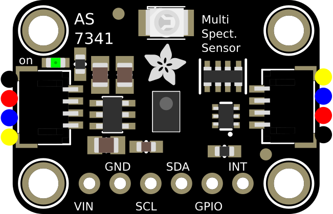
Pin Configuration and Descriptions

The Adafruit AS7341 breakout board has the following pins:

Pin Name Description
VIN Power input (3.3V to 5V). Powers the sensor and onboard voltage regulator.
GND Ground connection.
SCL I2C clock line. Connect to the SCL pin of your microcontroller.
SDA I2C data line. Connect to the SDA pin of your microcontroller.
INT Interrupt pin. Can be used to signal the microcontroller when data is ready.
RST Reset pin. Pull low to reset the sensor.
LED Controls the onboard LED for illumination during measurements.

Usage Instructions

Connecting the AS7341 to an Arduino UNO

To use the Adafruit AS7341 with an Arduino UNO, follow these steps:

  1. Wiring:

    • Connect the VIN pin to the 5V pin on the Arduino.
    • Connect the GND pin to the GND pin on the Arduino.
    • Connect the SCL pin to the A5 pin (I2C clock) on the Arduino.
    • Connect the SDA pin to the A4 pin (I2C data) on the Arduino.
  2. Install the Adafruit AS7341 Library:

    • Open the Arduino IDE.
    • Go to Sketch > Include Library > Manage Libraries.
    • Search for "Adafruit AS7341" and install the library.
  3. Example Code:
    Use the following example code to read data from the AS7341:

    #include <Wire.h>
    #include "Adafruit_AS7341.h"
    
    // Create an instance of the AS7341 sensor
    Adafruit_AS7341 as7341;
    
    void setup() {
      Serial.begin(115200);
      while (!Serial); // Wait for Serial Monitor to open
    
      // Initialize I2C communication and the sensor
      if (!as7341.begin()) {
        Serial.println("AS7341 not detected. Check wiring!");
        while (1); // Halt execution if sensor is not found
      }
    
      Serial.println("AS7341 initialized successfully!");
    }
    
    void loop() {
      // Read and print the visible light channels (F1-F6)
      Serial.println("Visible light channel readings:");
      for (int i = 1; i <= 6; i++) {
        Serial.print("F");
        Serial.print(i);
        Serial.print(": ");
        Serial.println(as7341.readChannel(i));
      }
    
      // Read and print the near-infrared (NIR) channel
      Serial.print("NIR: ");
      Serial.println(as7341.readChannel(7));
    
      // Read and print the clear channel
      Serial.print("Clear: ");
      Serial.println(as7341.readChannel(8));
    
      delay(1000); // Wait 1 second before the next reading
    }
    

Important Considerations

  • Power Supply: Ensure the sensor is powered with 3.3V logic levels. If using a 5V microcontroller, use level shifters for the I2C lines.
  • I2C Address: The default I2C address is 0x39. Ensure no other devices on the I2C bus share this address.
  • Illumination: For accurate color measurements, use the onboard LED or an external light source.

Troubleshooting and FAQs

Common Issues

  1. Sensor Not Detected:

    • Cause: Incorrect wiring or I2C address conflict.
    • Solution: Double-check the connections and ensure the I2C address matches the default (0x39).
  2. Inaccurate Readings:

    • Cause: Insufficient or inconsistent lighting.
    • Solution: Use a stable light source or the onboard LED for consistent measurements.
  3. Arduino Freezes or Crashes:

    • Cause: I2C communication issues.
    • Solution: Ensure proper pull-up resistors are present on the I2C lines (typically 4.7kΩ).

FAQs

  • Can the AS7341 measure UV light?
    No, the AS7341 is designed to measure visible and near-infrared light (350 nm to 1000 nm).

  • What is the purpose of the interrupt pin?
    The interrupt pin can signal the microcontroller when a measurement is complete, reducing the need for constant polling.

  • Can I use the AS7341 with a 5V microcontroller?
    Yes, but you must use level shifters for the I2C lines to avoid damaging the sensor.

This concludes the documentation for the Adafruit AS7341. For further details, refer to the official Adafruit guide or datasheet.