Cirkit Designer Logo
Cirkit Designer
Your all-in-one circuit design IDE
Home / 
Component Documentation

How to Use Adafruit Feather M0 Express: Examples, Pinouts, and Specs

Image of Adafruit Feather M0 Express
Cirkit Designer LogoDesign with Adafruit Feather M0 Express in Cirkit Designer

Introduction

The Adafruit Feather M0 Express is a versatile and compact development board designed for makers and hobbyists. It is based on the Atmel SAMD21G18A microcontroller and is equipped with a 32-bit ARM Cortex-M0+ processor. With 256 KB of flash memory and 32 KB of SRAM, it provides ample space for complex programs and data handling. The board's built-in USB support allows for easy programming and serial communication, while the microSD card slot enables additional storage for data logging or file storage. The Feather M0 Express is commonly used in projects requiring a powerful yet small microcontroller, such as wearable devices, portable instruments, and IoT applications.

Explore Projects Built with Adafruit Feather M0 Express

Use Cirkit Designer to design, explore, and prototype these projects online. Some projects support real-time simulation. Click "Open Project" to start designing instantly!
Solar-Powered Environmental Data Logger with Adafruit Feather M0 Express
Image of Lake Thoreau Monitoring Station: A project utilizing Adafruit Feather M0 Express in a practical application
This circuit is designed for environmental data collection and logging, utilizing an Adafruit Feather M0 Express microcontroller as the central processing unit. It interfaces with a BME280 sensor for atmospheric temperature, humidity, and pressure measurements, an SGP30 sensor for monitoring air quality (eCO2 and TVOC), and a STEMMA soil sensor for detecting soil moisture and temperature. The system is powered by a solar panel and a 3.7v LiPo battery, managed by an Adafruit BQ24074 Solar-DC-USB Lipo Charger, and provides easy access to the microcontroller's connections through an Adafruit Terminal Breakout FeatherWing.
Cirkit Designer LogoOpen Project in Cirkit Designer
Multi-Sensor Health Monitoring System with Adafruit Feather M0 Adalogger
Image of health tracker: A project utilizing Adafruit Feather M0 Express in a practical application
This circuit is designed to interface multiple sensors with an Adafruit Feather M0 Adalogger microcontroller for data logging purposes. The sensors include a MAX30205 temperature sensor, a body dehydration sensor, a MAX30102 pulse oximeter, an Adafruit LSM6DSOX 6-axis accelerometer and gyroscope, and an Adafruit BME680 environmental sensor. All sensors are connected to the microcontroller via an I2C bus, sharing the SDA and SCL lines for communication.
Cirkit Designer LogoOpen Project in Cirkit Designer
Touch-Sensitive Interface with Adafruit MPR121 and Feather 32u4 Bluefruit
Image of MPR121: A project utilizing Adafruit Feather M0 Express in a practical application
This circuit integrates an Adafruit MPR121 capacitive touch sensor with an Adafruit Feather 32u4 Bluefruit microcontroller. The MPR121 is powered by the Feather and communicates via I2C (SCL and SDA) to detect touch inputs, which can be processed or transmitted wirelessly by the Feather.
Cirkit Designer LogoOpen Project in Cirkit Designer
ESP32-Based Vibration Feedback System with Quad Alphanumeric Display and ADXL343 Accelerometer
Image of EC444 - Quest 3: A project utilizing Adafruit Feather M0 Express in a practical application
This circuit features an Adafruit HUZZAH32 ESP32 Feather board as the central microcontroller, which is connected to an Adafruit Quad AlphaNumeric Featherwing display and an Adafruit ADXL343 accelerometer via I2C communication (SCL and SDA lines). The ESP32 controls a vibration motor connected to one of its GPIO pins (A5_IO4) and shares a common power supply (3.3V) and ground (GND) with the other components. The purpose of this circuit is likely to read acceleration data, display information on the alphanumeric display, and provide haptic feedback through the vibration motor.
Cirkit Designer LogoOpen Project in Cirkit Designer

Explore Projects Built with Adafruit Feather M0 Express

Use Cirkit Designer to design, explore, and prototype these projects online. Some projects support real-time simulation. Click "Open Project" to start designing instantly!
Image of Lake Thoreau Monitoring Station: A project utilizing Adafruit Feather M0 Express in a practical application
Solar-Powered Environmental Data Logger with Adafruit Feather M0 Express
This circuit is designed for environmental data collection and logging, utilizing an Adafruit Feather M0 Express microcontroller as the central processing unit. It interfaces with a BME280 sensor for atmospheric temperature, humidity, and pressure measurements, an SGP30 sensor for monitoring air quality (eCO2 and TVOC), and a STEMMA soil sensor for detecting soil moisture and temperature. The system is powered by a solar panel and a 3.7v LiPo battery, managed by an Adafruit BQ24074 Solar-DC-USB Lipo Charger, and provides easy access to the microcontroller's connections through an Adafruit Terminal Breakout FeatherWing.
Cirkit Designer LogoOpen Project in Cirkit Designer
Image of health tracker: A project utilizing Adafruit Feather M0 Express in a practical application
Multi-Sensor Health Monitoring System with Adafruit Feather M0 Adalogger
This circuit is designed to interface multiple sensors with an Adafruit Feather M0 Adalogger microcontroller for data logging purposes. The sensors include a MAX30205 temperature sensor, a body dehydration sensor, a MAX30102 pulse oximeter, an Adafruit LSM6DSOX 6-axis accelerometer and gyroscope, and an Adafruit BME680 environmental sensor. All sensors are connected to the microcontroller via an I2C bus, sharing the SDA and SCL lines for communication.
Cirkit Designer LogoOpen Project in Cirkit Designer
Image of MPR121: A project utilizing Adafruit Feather M0 Express in a practical application
Touch-Sensitive Interface with Adafruit MPR121 and Feather 32u4 Bluefruit
This circuit integrates an Adafruit MPR121 capacitive touch sensor with an Adafruit Feather 32u4 Bluefruit microcontroller. The MPR121 is powered by the Feather and communicates via I2C (SCL and SDA) to detect touch inputs, which can be processed or transmitted wirelessly by the Feather.
Cirkit Designer LogoOpen Project in Cirkit Designer
Image of EC444 - Quest 3: A project utilizing Adafruit Feather M0 Express in a practical application
ESP32-Based Vibration Feedback System with Quad Alphanumeric Display and ADXL343 Accelerometer
This circuit features an Adafruit HUZZAH32 ESP32 Feather board as the central microcontroller, which is connected to an Adafruit Quad AlphaNumeric Featherwing display and an Adafruit ADXL343 accelerometer via I2C communication (SCL and SDA lines). The ESP32 controls a vibration motor connected to one of its GPIO pins (A5_IO4) and shares a common power supply (3.3V) and ground (GND) with the other components. The purpose of this circuit is likely to read acceleration data, display information on the alphanumeric display, and provide haptic feedback through the vibration motor.
Cirkit Designer LogoOpen Project in Cirkit Designer

Technical Specifications

Key Technical Details

  • Microcontroller: Atmel SAMD21G18A
  • Processor: 32-bit ARM Cortex-M0+ running at 48 MHz
  • Flash Memory: 256 KB
  • SRAM: 32 KB
  • Operating Voltage: 3.3V
  • I/O Pins: 20 GPIO pins
  • Analog Inputs: 6 12-bit ADC channels
  • Analog Outputs: 1 10-bit DAC
  • PWM: Yes, available on certain pins
  • UART: 1
  • I2C: 1
  • SPI: 1
  • External Interrupts: Available on all pins
  • DC Current per I/O Pin: 7 mA
  • USB: Micro-USB interface for programming and power
  • Battery Charging: Built-in charging circuit for 3.7V LiPo batteries
  • Dimensions: 51mm x 23mm x 8mm (without headers)

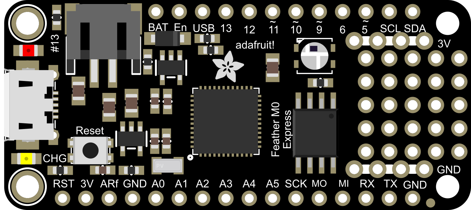
Pin Configuration and Descriptions

Pin # Function Description
1 GND Ground
2 BAT Battery positive voltage (for LiPo batteries)
3 EN Enable pin for the 3.3V regulator
4 USB USB positive voltage from the micro-USB port
5-12 Digital I/O Digital input/output pins, PWM capable on some
13-18 Analog Inputs Analog input pins, also digital I/O capable
19 AREF Analog reference voltage for ADC
20 DAC Digital-to-Analog Converter output
21 SCK SPI clock
22 MISO SPI Master In Slave Out
23 MOSI SPI Master Out Slave In
24 SDA I2C Data
25 SCL I2C Clock
26 RX UART Receive
27 TX UART Transmit
28 RST Reset pin
29 3V 3.3V output from the regulator
30 13 Built-in LED, also digital I/O pin

Usage Instructions

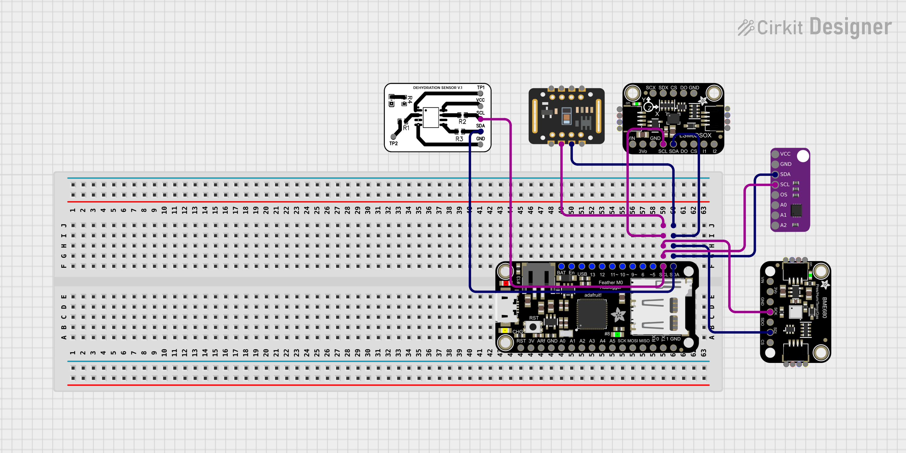
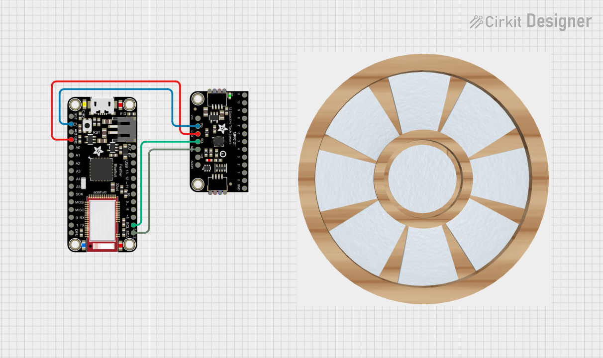
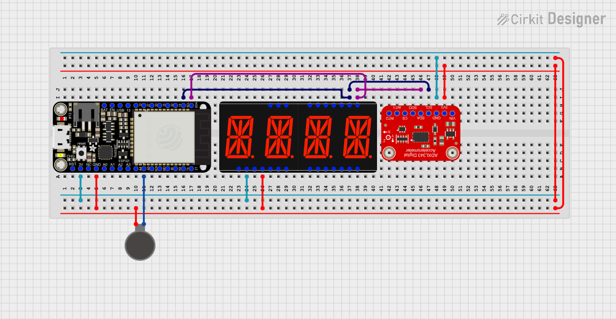
Integrating with a Circuit

To use the Adafruit Feather M0 Express in a circuit:

  1. Connect the board to your computer using a micro-USB cable.
  2. Ensure that the board's drivers and the Arduino IDE are installed on your computer.
  3. Select the correct board from the Tools > Board menu in the Arduino IDE.
  4. Connect external components to the GPIO pins as required for your project.

Important Considerations and Best Practices

  • Power Supply: Ensure that the power supply is within the recommended voltage range to prevent damage.
  • I/O Pin Limits: Do not exceed the maximum current rating for the I/O pins.
  • Static Discharge: Handle the board with care to avoid static discharge that can damage the microcontroller.
  • Battery Charging: When using a LiPo battery, ensure it is connected correctly to the BAT pin and never charge the battery unattended.

Example Code for Arduino UNO

Here is a simple example of how to blink the built-in LED on the Adafruit Feather M0 Express using the Arduino IDE:

// Define the built-in LED pin
#define LED_BUILTIN 13

void setup() {
  // Initialize the LED pin as an output
  pinMode(LED_BUILTIN, OUTPUT);
}

void loop() {
  // Turn the LED on
  digitalWrite(LED_BUILTIN, HIGH);
  // Wait for one second
  delay(1000);
  // Turn the LED off
  digitalWrite(LED_BUILTIN, LOW);
  // Wait for one second
  delay(1000);
}

Troubleshooting and FAQs

Common Issues

  • Board Not Recognized: Ensure that the correct drivers are installed and the USB cable is functioning.
  • Sketch Not Uploading: Check the selected board and port in the Arduino IDE. Press the reset button on the board and try again.
  • Incorrect Behavior: Verify that the wiring is correct and that the code corresponds to the connected hardware.

Solutions and Tips

  • Driver Installation: Visit the Adafruit website for the latest drivers and installation guides.
  • Quality USB Cable: Use a high-quality USB cable capable of data transfer, not just charging.
  • Reset Button: Use the reset button to enter bootloader mode if the board is not responding.

FAQs

Q: Can I power the Feather M0 Express with a battery? A: Yes, you can use a 3.7V LiPo battery connected to the BAT pin.

Q: What is the maximum voltage that can be applied to the analog pins? A: The maximum voltage for the analog pins is 3.3V.

Q: Can I use the Feather M0 Express with the Arduino IDE? A: Yes, the Feather M0 Express is fully compatible with the Arduino IDE.

Q: How do I charge a connected LiPo battery? A: The Feather M0 Express has a built-in charging circuit. Simply connect the board to a USB power source while the battery is connected to the BAT pin.