How to Use Pulse Sensor: Examples, Pinouts, and Specs
Introduction
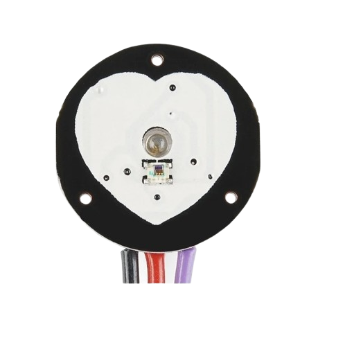
The Pulse Sensor Amped by X-MIND TECH is a small, lightweight device designed to detect and measure an individual's heartbeat. Using optical technology, it monitors blood flow through the skin and provides real-time heart rate data. This sensor is ideal for applications such as fitness tracking, biofeedback, and medical monitoring. Its compact design and ease of use make it suitable for both hobbyists and professionals.
Explore Projects Built with Pulse Sensor
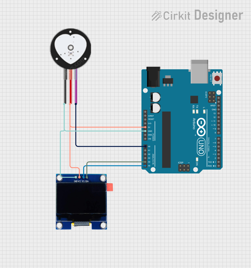
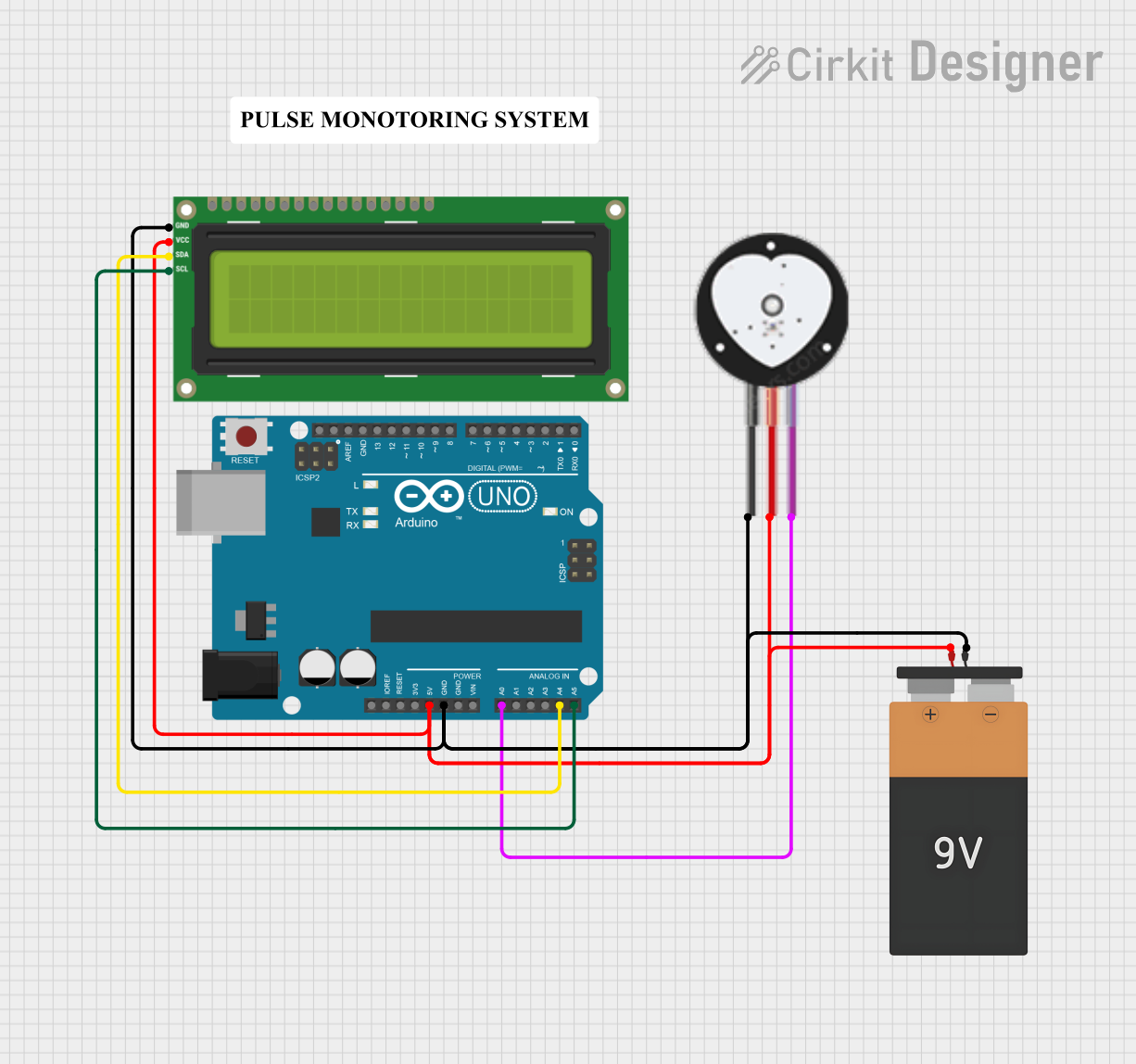
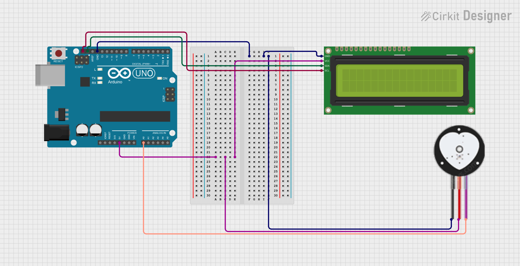
Explore Projects Built with Pulse Sensor
Common Applications
- Fitness trackers and wearable devices
- Heart rate monitoring in medical applications
- Biofeedback systems
- DIY electronics and Arduino projects
- Stress and emotion monitoring systems
Technical Specifications
The following table outlines the key technical details of the Pulse Sensor Amped:
| Parameter | Value |
|---|---|
| Manufacturer | X-MIND TECH |
| Part ID | Pulse Sensor Amped |
| Operating Voltage | 3.3V to 5V |
| Current Consumption | ~4mA |
| Output Signal | Analog (0-1023 for 10-bit ADC) |
| Sensor Type | Optical (PPG - Photoplethysmography) |
| Dimensions | 0.625 inches (16mm) in diameter |
| Cable Length | ~24 inches (60cm) |
| Weight | ~3 grams |
Pin Configuration
The Pulse Sensor Amped has a 3-pin interface. The pinout is as follows:
| Pin | Name | Description |
|---|---|---|
| 1 | VCC | Power supply input (3.3V to 5V) |
| 2 | GND | Ground connection |
| 3 | Signal | Analog output signal representing heart rate data |
Usage Instructions
Connecting the Pulse Sensor
To use the Pulse Sensor Amped in a circuit, follow these steps:
- Power the Sensor: Connect the
VCCpin to a 3.3V or 5V power source and theGNDpin to the ground of your circuit. - Read the Signal: Connect the
Signalpin to an analog input pin of your microcontroller (e.g., Arduino). - Secure the Sensor: Attach the sensor to a fingertip or earlobe using the included Velcro strap or adhesive.
Important Considerations
- Ambient Light: The sensor is sensitive to ambient light. Ensure it is properly shielded from external light sources for accurate readings.
- Placement: For best results, place the sensor on a location with good blood flow, such as a fingertip or earlobe.
- Signal Smoothing: Use a low-pass filter or software-based smoothing to reduce noise in the signal.
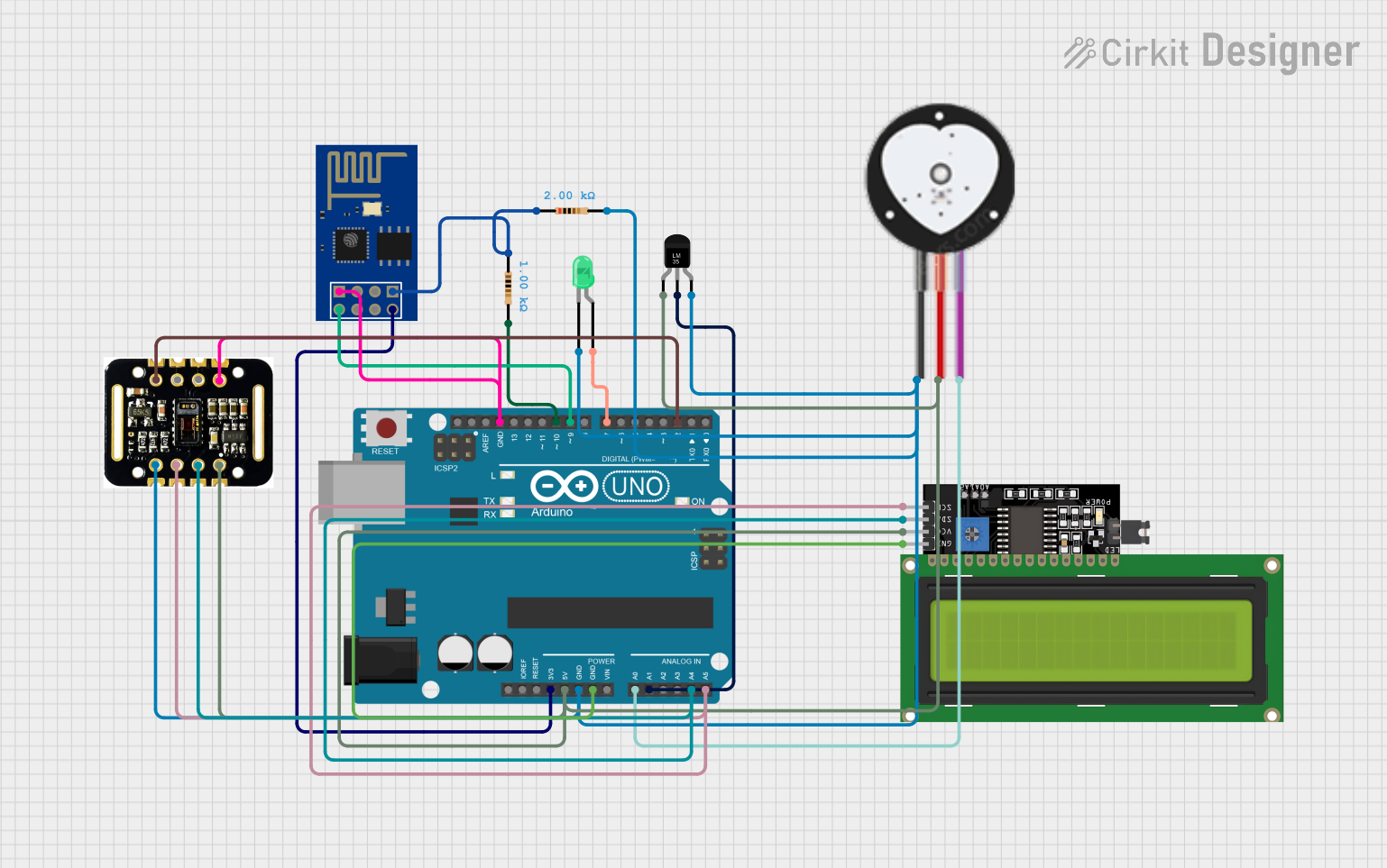
Example: Using the Pulse Sensor with Arduino UNO
Below is an example of how to use the Pulse Sensor Amped with an Arduino UNO:
// Include the Pulse Sensor library
// Download the library from: https://github.com/WorldFamousElectronics/PulseSensor_Amped_Arduino

#include <PulseSensorPlayground.h>

// Define the analog pin connected to the Pulse Sensor
const int PULSE_PIN = A0;

// Create a PulseSensorPlayground object
PulseSensorPlayground pulseSensor;

// Variable to store the heart rate
int heartRate;

void setup() {
  // Initialize serial communication for debugging
  Serial.begin(9600);

  // Configure the Pulse Sensor
  pulseSensor.analogInput(PULSE_PIN);
  pulseSensor.setSerial(Serial); // Optional: Output data to Serial Monitor

  // Start the Pulse Sensor
  if (pulseSensor.begin()) {
    Serial.println("Pulse Sensor initialized successfully!");
  } else {
    Serial.println("Failed to initialize Pulse Sensor.");
  }
}

void loop() {
  // Read the heart rate
  heartRate = pulseSensor.getBeatsPerMinute();

  // Check if a valid heart rate is detected
  if (pulseSensor.sawStartOfBeat()) {
    Serial.print("Heart Rate: ");
    Serial.print(heartRate);
    Serial.println(" BPM");
  }

  // Add a small delay to stabilize readings
  delay(20);
}
Notes:
- Install the PulseSensorPlayground library before running the code.
- Use the Serial Monitor (set to 9600 baud) to view the heart rate data.
Troubleshooting and FAQs
Common Issues
No Signal Detected:
- Ensure the sensor is properly connected to the microcontroller.
- Verify that the sensor is placed on a location with good blood flow.
- Check for loose or damaged wires.
Inconsistent Readings:
- Shield the sensor from ambient light.
- Ensure the sensor is securely attached to the skin.
- Use software filtering to smooth out noise.
Sensor Not Initializing:
- Confirm that the
VCCandGNDpins are correctly connected. - Verify the operating voltage (3.3V to 5V).
- Confirm that the
FAQs
Q: Can the Pulse Sensor be used with a Raspberry Pi?
A: Yes, but since the Raspberry Pi lacks an analog input, you will need an external ADC (Analog-to-Digital Converter) to read the sensor's output.
Q: How do I clean the sensor?
A: Use a soft, damp cloth to gently clean the sensor surface. Avoid using harsh chemicals or submerging the sensor in water.
Q: What is the maximum heart rate the sensor can detect?
A: The sensor can typically detect heart rates up to 220 BPM, depending on the signal quality and placement.
Q: Can I use multiple Pulse Sensors in the same project?
A: Yes, but each sensor must be connected to a separate analog input pin on your microcontroller.
By following this documentation, you can effectively integrate the Pulse Sensor Amped into your projects and achieve accurate heart rate monitoring.