How to Use Voltage Devider: Examples, Pinouts, and Specs
Introduction
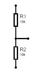
A voltage divider is a simple yet essential electronic circuit used to reduce a higher voltage to a lower voltage. It consists of two resistors connected in series, with the output voltage taken from the junction between the two resistors. The voltage divider operates based on the principle of resistive voltage division, where the output voltage is proportional to the ratio of the two resistors.
Explore Projects Built with Voltage Devider


Explore Projects Built with Voltage Devider
Common Applications and Use Cases
- Signal Level Adjustment: Scaling down voltage levels for sensors or microcontroller inputs.
- Reference Voltage Generation: Providing a stable reference voltage for analog circuits.
- Battery Monitoring: Measuring battery voltage by stepping it down to a measurable range.
- Biasing Circuits: Setting operating points for transistors or amplifiers.
Technical Specifications
The voltage divider circuit is defined by the following formula:
[ V_{out} = V_{in} \times \frac{R_2}{R_1 + R_2} ]
Where:
- ( V_{in} ): Input voltage
- ( V_{out} ): Output voltage
- ( R_1 ): Resistor connected to the input voltage
- ( R_2 ): Resistor connected to ground
Key Technical Details
- Input Voltage Range: Depends on the resistor ratings and power dissipation.
- Output Voltage Range: Determined by the resistor ratio and input voltage.
- Power Dissipation: Ensure resistors can handle the power calculated as ( P = I^2 \times R ).
- Accuracy: Dependent on resistor tolerances (e.g., ±1%, ±5%).
Pin Configuration and Descriptions
A voltage divider does not have pins like an IC but consists of two resistors connected as follows:
| Pin/Connection | Description |
|---|---|
| ( V_{in} ) | Input voltage to the circuit |
| ( V_{out} ) | Output voltage from the resistor junction |
| Ground | Common ground connection |
Usage Instructions
How to Use the Voltage Divider in a Circuit
Select Resistor Values:
- Choose ( R_1 ) and ( R_2 ) based on the desired output voltage using the formula: [ V_{out} = V_{in} \times \frac{R_2}{R_1 + R_2} ]
- Ensure the resistors can handle the power dissipation.
Connect the Circuit:
- Connect ( R_1 ) between the input voltage (( V_{in} )) and the junction point.
- Connect ( R_2 ) between the junction point and ground.
- Take the output voltage (( V_{out} )) from the junction point.
Verify the Output:
- Measure the output voltage using a multimeter to ensure it matches the calculated value.
Important Considerations and Best Practices
- Resistor Tolerance: Use resistors with low tolerance (e.g., ±1%) for higher accuracy.
- Power Dissipation: Ensure resistors can handle the power dissipation to avoid overheating.
- Input Impedance: Avoid loading the circuit with low-impedance devices, as this can affect the output voltage.
- High Impedance Loads: For circuits with high impedance, consider adding a buffer (e.g., an op-amp) to stabilize the output voltage.
Example: Using a Voltage Divider with Arduino UNO
To measure a 12V battery voltage using an Arduino UNO (which has a 5V ADC input limit), you can use a voltage divider to step down the voltage.
Circuit Design
- ( R_1 = 10k\Omega )
- ( R_2 = 5k\Omega )
- Input Voltage (( V_{in} )): 12V
- Output Voltage (( V_{out} )): ( 12 \times \frac{5}{10 + 5} = 4V )
Arduino Code
// Define the analog pin connected to the voltage divider
const int voltagePin = A0;

// Define the resistor values in the voltage divider
const float R1 = 10000.0; // 10k ohms
const float R2 = 5000.0;  // 5k ohms

void setup() {
  Serial.begin(9600); // Initialize serial communication
}

void loop() {
  int sensorValue = analogRead(voltagePin); // Read the ADC value
  float voltage = sensorValue * (5.0 / 1023.0); // Convert ADC value to voltage

  // Calculate the input voltage using the voltage divider formula
  float inputVoltage = voltage * ((R1 + R2) / R2);

  // Print the input voltage to the Serial Monitor
  Serial.print("Input Voltage: ");
  Serial.print(inputVoltage);
  Serial.println(" V");

  delay(1000); // Wait for 1 second before the next reading
}
Troubleshooting and FAQs
Common Issues
Incorrect Output Voltage:
- Cause: Incorrect resistor values or connections.
- Solution: Double-check the resistor values and wiring.
Overheating Resistors:
- Cause: Resistors are dissipating more power than their rating.
- Solution: Use resistors with higher power ratings.
Output Voltage Fluctuations:
- Cause: High impedance load or noise in the circuit.
- Solution: Add a capacitor across ( R_2 ) to filter noise or use a buffer.
Arduino Reads Incorrect Voltage:
- Cause: Incorrect scaling in the code or noisy input.
- Solution: Verify the resistor ratio and ensure proper grounding.
FAQs
Q1: Can I use a voltage divider to power a device?
A1: Voltage dividers are not suitable for powering devices, as they cannot provide significant current. Use a voltage regulator instead.
Q2: How do I choose resistor values for a voltage divider?
A2: Select resistors based on the desired output voltage and ensure their combined resistance does not draw excessive current from the source.
Q3: What happens if I reverse ( R_1 ) and ( R_2 )?
A3: Reversing the resistors will change the output voltage. Ensure the resistors are connected as per the desired voltage ratio.
Q4: Can I use a potentiometer as a voltage divider?
A4: Yes, a potentiometer can act as an adjustable voltage divider, allowing you to vary the output voltage.