How to Use Holybro telemetry 433mhz: Examples, Pinouts, and Specs
Introduction
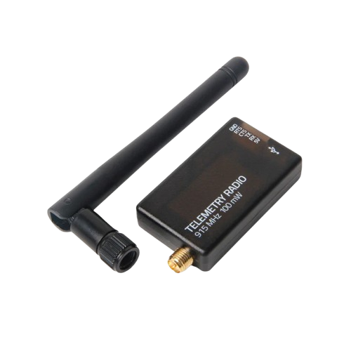
The Holybro Telemetry 433MHz (V3) is a wireless telemetry system designed for seamless communication between drones and ground stations. Operating at 433 MHz, this system enables real-time data transmission, including critical information such as altitude, speed, and battery status. It is widely used in UAV (Unmanned Aerial Vehicle) applications, robotics, and other remote monitoring systems.
Explore Projects Built with Holybro telemetry 433mhz


Explore Projects Built with Holybro telemetry 433mhz
Common Applications and Use Cases
- Real-time telemetry for drones and UAVs
- Remote monitoring of robotic systems
- Data transmission for IoT devices
- Ground station communication for RC vehicles
Technical Specifications
Key Technical Details
| Parameter | Value |
|---|---|
| Operating Frequency | 433 MHz |
| Transmission Power | Up to 100 mW |
| Communication Protocol | MAVLink |
| Range | Up to 1.5 km (line of sight) |
| Input Voltage | 5V |
| Interface | UART (Universal Asynchronous Receiver-Transmitter) |
| Dimensions | 25 mm x 55 mm x 12 mm |
| Weight | 15 g |
Pin Configuration and Descriptions
Telemetry Module Pinout
| Pin Number | Pin Name | Description |
|---|---|---|
| 1 | VCC | Power input (5V) |
| 2 | GND | Ground connection |
| 3 | TX | Transmit data (UART output) |
| 4 | RX | Receive data (UART input) |
| 5 | CTS | Clear to Send (flow control, optional) |
| 6 | RTS | Ready to Send (flow control, optional) |
USB Adapter Pinout (for Ground Station)
| Pin Number | Pin Name | Description |
|---|---|---|
| 1 | VCC | Power input (5V from USB) |
| 2 | GND | Ground connection |
| 3 | TX | Transmit data to the telemetry module |
| 4 | RX | Receive data from the telemetry module |
Usage Instructions
How to Use the Component in a Circuit
Connecting the Module to a Flight Controller:
- Connect the
TXpin of the telemetry module to theRXpin of the flight controller. - Connect the
RXpin of the telemetry module to theTXpin of the flight controller. - Provide 5V power to the
VCCpin and connect theGNDpin to the ground of the flight controller.
- Connect the
Setting Up the Ground Station:
- Plug the USB adapter into your computer.
- Install the necessary drivers (if required) for the USB adapter.
- Use ground station software (e.g., Mission Planner or QGroundControl) to establish a connection.
Configuring the Telemetry System:
- Ensure both the air module (on the drone) and the ground module (USB adapter) are set to the same baud rate (default: 57600 bps).
- Verify that both modules are paired and operating on the same frequency.
Important Considerations and Best Practices
- Antenna Placement: Ensure the antennas are securely connected and positioned to avoid interference. Keep them away from high-power electronics or metal objects.
- Power Supply: Use a stable 5V power source to avoid communication issues.
- Line of Sight: For maximum range, maintain a clear line of sight between the air and ground modules.
- Firmware Updates: Periodically check for firmware updates from Holybro to ensure optimal performance.
Example Code for Arduino UNO
The Holybro Telemetry 433MHz module can be connected to an Arduino UNO for testing or custom applications. Below is an example code snippet to send and receive data:
#include <SoftwareSerial.h>

// Define RX and TX pins for the telemetry module
SoftwareSerial telemetry(10, 11); // RX = Pin 10, TX = Pin 11

void setup() {
  // Initialize serial communication for debugging
  Serial.begin(9600);
  // Initialize telemetry communication
  telemetry.begin(57600); // Default baud rate for the module

  Serial.println("Telemetry module initialized.");
}

void loop() {
  // Send data to the telemetry module
  telemetry.println("Hello from Arduino!");

  // Check if data is available from the telemetry module
  if (telemetry.available()) {
    String receivedData = telemetry.readString();
    // Print received data to the Serial Monitor
    Serial.println("Received: " + receivedData);
  }

  delay(1000); // Wait for 1 second
}
Notes:
- Connect the
TXpin of the telemetry module to pin 10 of the Arduino, and theRXpin to pin 11. - Ensure the Arduino is powered properly and the telemetry module is connected securely.
Troubleshooting and FAQs
Common Issues and Solutions
No Communication Between Modules:
- Ensure both modules are powered and the antennas are connected.
- Verify that the baud rates match on both the air and ground modules.
- Check for physical damage to the module or cables.
Short Range or Signal Loss:
- Ensure a clear line of sight between the modules.
- Avoid interference from other devices operating at 433 MHz.
- Check the antenna connections and replace the antenna if necessary.
Ground Station Software Not Detecting the Module:
- Confirm that the USB adapter drivers are installed correctly.
- Try a different USB port or cable.
- Restart the ground station software and re-scan for devices.
FAQs
Q: Can I use this module with a 3.3V flight controller?
A: No, the module requires a 5V power supply. Use a level shifter if your flight controller operates at 3.3V logic levels.
Q: What is the maximum range of the module?
A: The module can achieve up to 1.5 km range in ideal conditions with a clear line of sight.
Q: Can I use this module with other communication protocols?
A: The module is designed to work with MAVLink protocol. Using other protocols may require additional configuration or firmware modifications.
Q: How do I update the firmware?
A: Firmware updates can be performed using the Holybro firmware update tool. Follow the instructions provided on the Holybro website.
Q: Is this module compatible with 915 MHz systems?
A: No, this module operates at 433 MHz and is not compatible with 915 MHz systems. Ensure you select the correct frequency for your region and application.
By following this documentation, users can effectively integrate and troubleshoot the Holybro Telemetry 433MHz (V3) module in their projects.