How to Use UPS: Examples, Pinouts, and Specs
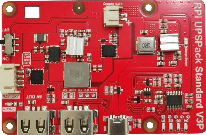
Introduction
A Uninterruptible Power Supply (UPS) is an electronic device designed to provide backup power to connected devices during power outages or fluctuations. It ensures the continuous operation of critical systems by supplying power from its internal battery when the main power source fails. Additionally, a UPS protects sensitive electronics from power surges, voltage drops, and other electrical disturbances.
Common applications of a UPS include:
- Powering computers, servers, and networking equipment during outages.
- Protecting medical devices and critical systems in hospitals.
- Ensuring uninterrupted operation of industrial machinery and automation systems.
- Safeguarding home entertainment systems and gaming consoles from power surges.
Explore Projects Built with UPS


Explore Projects Built with UPS
Technical Specifications
Below are the general technical specifications for a typical UPS. Note that specific models may vary in their ratings and features.
| Specification | Details |
|---|---|
| Input Voltage Range | 110V - 240V AC |
| Output Voltage | 110V - 240V AC (depending on the model) |
| Output Power Capacity | 300W to 10,000W (varies by model) |
| Battery Type | Sealed Lead Acid (SLA) or Lithium-ion |
| Battery Backup Time | 5 minutes to several hours (depending on load and battery capacity) |
| Transfer Time | Typically <10ms (time to switch to battery power during an outage) |
| Surge Protection Rating | 300 to 1000 Joules |
| Communication Interface | USB, RS232, or Ethernet (for monitoring and control) |
| Operating Temperature | 0°C to 40°C |
| Dimensions and Weight | Varies by model (e.g., 10kg for small units, 50kg+ for larger systems) |
Pin Configuration and Descriptions
For UPS models with communication ports (e.g., USB or RS232), the pin configuration is as follows:
RS232 Port Pinout
| Pin Number | Signal Name | Description |
|---|---|---|
| 1 | DCD | Data Carrier Detect |
| 2 | RXD | Receive Data (from UPS to external device) |
| 3 | TXD | Transmit Data (from external device to UPS) |
| 4 | DTR | Data Terminal Ready |
| 5 | GND | Ground |
| 6 | DSR | Data Set Ready |
| 7 | RTS | Request to Send |
| 8 | CTS | Clear to Send |
| 9 | RI | Ring Indicator |
USB Port Pinout
| Pin Number | Signal Name | Description |
|---|---|---|
| 1 | VBUS | +5V Power Supply |
| 2 | D- | Data Negative |
| 3 | D+ | Data Positive |
| 4 | GND | Ground |
Usage Instructions
How to Use a UPS in a Circuit
- Connect the UPS to the Power Source: Plug the UPS into a wall outlet using the provided power cable.
- Connect Devices to the UPS: Plug your electronic devices (e.g., computer, router) into the UPS output sockets. Ensure the total power consumption of connected devices does not exceed the UPS's rated capacity.
- Turn On the UPS: Press the power button to activate the UPS. Most models will perform a self-test to ensure proper functionality.
- Monitor the UPS: Use the built-in display or communication interface (e.g., USB or RS232) to monitor battery status, load percentage, and other parameters.
Important Considerations and Best Practices
- Load Management: Do not exceed the UPS's maximum power capacity. Overloading can cause the UPS to shut down or fail.
- Battery Maintenance: Periodically check the battery health and replace it as recommended by the manufacturer (typically every 3-5 years).
- Ventilation: Place the UPS in a well-ventilated area to prevent overheating.
- Testing: Regularly test the UPS by simulating a power outage to ensure it functions correctly.
- Grounding: Ensure the UPS is properly grounded to avoid electrical hazards.
Example: Monitoring a UPS with Arduino UNO
Some UPS models support communication via RS232 or USB. Below is an example of how to monitor a UPS's status using an Arduino UNO and an RS232-to-TTL converter.
#include <SoftwareSerial.h>

// Define RX and TX pins for RS232 communication
SoftwareSerial upsSerial(10, 11); // RX = pin 10, TX = pin 11

void setup() {
  Serial.begin(9600); // Initialize Serial Monitor
  upsSerial.begin(9600); // Initialize UPS communication

  Serial.println("UPS Monitoring Started");
}

void loop() {
  // Check if data is available from the UPS
  if (upsSerial.available()) {
    String upsData = "";
    while (upsSerial.available()) {
      char c = upsSerial.read(); // Read one character at a time
      upsData += c; // Append character to the string
    }
    // Print the received data to the Serial Monitor
    Serial.println("UPS Data: " + upsData);
  }

  delay(1000); // Wait for 1 second before checking again
}
Note: Ensure the UPS supports RS232 communication and configure the baud rate as per the UPS's specifications.
Troubleshooting and FAQs
Common Issues and Solutions
UPS Does Not Turn On
- Cause: Battery is discharged or faulty.
- Solution: Charge the battery for several hours or replace it if necessary.
Devices Connected to the UPS Shut Down During an Outage
- Cause: The load exceeds the UPS's capacity.
- Solution: Reduce the number of connected devices or use a higher-capacity UPS.
Frequent Beeping from the UPS
- Cause: Low battery or overload condition.
- Solution: Check the battery status and reduce the load if needed.
UPS Overheats
- Cause: Poor ventilation or excessive load.
- Solution: Ensure proper airflow around the UPS and reduce the load.
Communication with the UPS Fails
- Cause: Incorrect wiring or incompatible settings.
- Solution: Verify the pin connections and communication parameters (e.g., baud rate).
FAQs
Q: Can I connect a laser printer to a UPS?
- A: It is not recommended, as laser printers have high power surges that can overload the UPS.
Q: How long will a UPS provide backup power?
- A: Backup time depends on the battery capacity and the load. For example, a 600VA UPS may provide 10-15 minutes of backup for a typical desktop computer.
Q: Can I replace the UPS battery myself?
- A: Yes, but follow the manufacturer's instructions and safety precautions.
Q: Is it safe to use a UPS with a generator?
- A: Yes, but ensure the generator provides stable voltage and frequency within the UPS's input range.