How to Use Pmod BTN: 4 User Pushbuttons: Examples, Pinouts, and Specs
Introduction
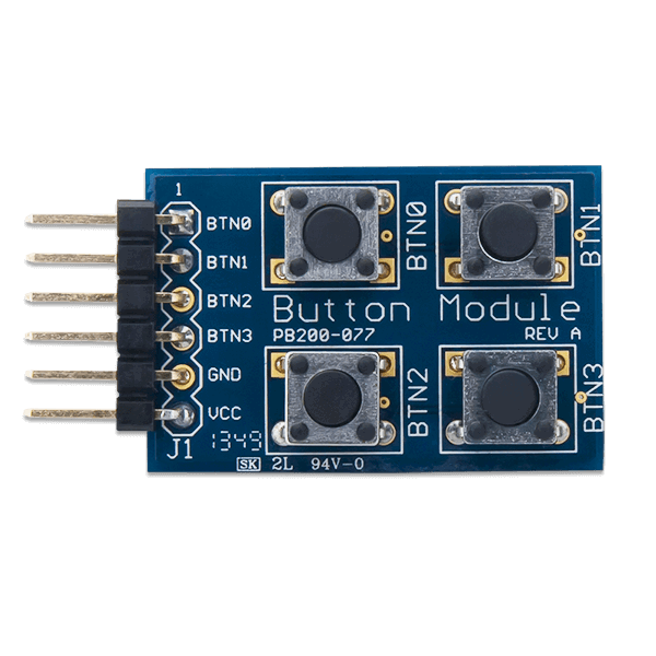
The Pmod BTN is a versatile input module manufactured by Digilent, featuring four user pushbuttons. This module allows users to interact with electronic circuits by pressing the buttons, making it ideal for applications requiring manual input. The Pmod BTN is commonly used in prototyping, educational projects, and embedded systems to provide a simple and reliable way to capture user input.
Explore Projects Built with Pmod BTN: 4 User Pushbuttons


Explore Projects Built with Pmod BTN: 4 User Pushbuttons
Common Applications and Use Cases
- User input for microcontroller-based projects
- Menu navigation in embedded systems
- Triggering events or actions in digital circuits
- Educational tools for learning about digital input handling
Technical Specifications
The Pmod BTN is designed to interface seamlessly with microcontrollers and FPGAs. Below are its key technical details:
Key Specifications
- Manufacturer Part ID: 1286-1145-ND
- Number of Buttons: 4
- Interface: GPIO (General Purpose Input/Output)
- Operating Voltage: 3.3V or 5V (compatible with most microcontrollers)
- Connector: 6-pin Pmod header
- Dimensions: 0.8" × 0.8" (20.32mm × 20.32mm)
Pin Configuration and Descriptions
The Pmod BTN uses a 6-pin header for connection. The pinout is as follows:
| Pin Number | Pin Name | Description |
|---|---|---|
| 1 | BTN1 | Output signal for Button 1 |
| 2 | BTN2 | Output signal for Button 2 |
| 3 | BTN3 | Output signal for Button 3 |
| 4 | BTN4 | Output signal for Button 4 |
| 5 | GND | Ground |
| 6 | VCC | Power supply (3.3V or 5V) |
Usage Instructions
The Pmod BTN is straightforward to use in a circuit. Follow the steps below to integrate it into your project:
Connecting the Pmod BTN
- Power Supply: Connect the VCC pin to the 3.3V or 5V power supply of your microcontroller or FPGA.
- Ground: Connect the GND pin to the ground of your system.
- Button Outputs: Connect the BTN1, BTN2, BTN3, and BTN4 pins to GPIO pins on your microcontroller or FPGA.
Reading Button States
Each button on the Pmod BTN outputs a digital signal:
- High (1): Button is not pressed.
- Low (0): Button is pressed.
Example: Using Pmod BTN with Arduino UNO
Below is an example of how to use the Pmod BTN with an Arduino UNO to read button states and print them to the Serial Monitor.
// Define the pins connected to the Pmod BTN
const int btn1Pin = 2; // Button 1 connected to digital pin 2
const int btn2Pin = 3; // Button 2 connected to digital pin 3
const int btn3Pin = 4; // Button 3 connected to digital pin 4
const int btn4Pin = 5; // Button 4 connected to digital pin 5

void setup() {
  // Initialize serial communication
  Serial.begin(9600);

  // Set button pins as inputs with pull-up resistors
  pinMode(btn1Pin, INPUT_PULLUP);
  pinMode(btn2Pin, INPUT_PULLUP);
  pinMode(btn3Pin, INPUT_PULLUP);
  pinMode(btn4Pin, INPUT_PULLUP);
}

void loop() {
  // Read the state of each button
  int btn1State = digitalRead(btn1Pin);
  int btn2State = digitalRead(btn2Pin);
  int btn3State = digitalRead(btn3Pin);
  int btn4State = digitalRead(btn4Pin);

  // Print button states to the Serial Monitor
  Serial.print("BTN1: ");
  Serial.print(btn1State == LOW ? "Pressed" : "Released");
  Serial.print(" | BTN2: ");
  Serial.print(btn2State == LOW ? "Pressed" : "Released");
  Serial.print(" | BTN3: ");
  Serial.print(btn3State == LOW ? "Pressed" : "Released");
  Serial.print(" | BTN4: ");
  Serial.println(btn4State == LOW ? "Pressed" : "Released");

  // Add a small delay to avoid spamming the Serial Monitor
  delay(200);
}
Important Considerations and Best Practices
- Debouncing: Mechanical pushbuttons can produce noise or "bouncing" when pressed. Use software debouncing techniques or external capacitors to ensure stable readings.
- Voltage Compatibility: Ensure the Pmod BTN's VCC pin matches the voltage level of your microcontroller (3.3V or 5V).
- Pull-up Resistors: The Arduino example uses internal pull-up resistors. If using other microcontrollers, ensure pull-up resistors are enabled or added externally.
Troubleshooting and FAQs
Common Issues
No Response from Buttons
- Cause: Incorrect wiring or loose connections.
- Solution: Double-check the connections, ensuring VCC, GND, and button output pins are properly connected.
Button States Fluctuate Rapidly
- Cause: Button bouncing.
- Solution: Implement software debouncing in your code or add a small capacitor (e.g., 0.1µF) across each button.
Incorrect Voltage Levels
- Cause: Mismatch between the Pmod BTN's VCC and the microcontroller's logic level.
- Solution: Verify that the Pmod BTN is powered with the correct voltage (3.3V or 5V).
FAQs
Q: Can I use the Pmod BTN with a Raspberry Pi?
A: Yes, the Pmod BTN can be used with a Raspberry Pi. Connect the button output pins to GPIO pins on the Raspberry Pi and use pull-up resistors (internal or external) to read the button states.
Q: Do I need external pull-up resistors?
A: If your microcontroller does not have internal pull-up resistors, you will need to add external pull-up resistors (e.g., 10kΩ) to each button output pin.
Q: Can I use fewer than 4 buttons?
A: Yes, you can use only the buttons you need. Leave the unused button output pins unconnected.
By following this documentation, you can effectively integrate the Pmod BTN into your projects and troubleshoot any issues that arise.