How to Use esp32 38p typec cp2102: Examples, Pinouts, and Specs
Introduction
The ESP32 38P Type-C CP2102 is a versatile and powerful microcontroller module developed by Espressif Systems. It is based on the ESP32 dual-core processor, which integrates Wi-Fi and Bluetooth capabilities, making it ideal for IoT (Internet of Things) applications. This module features a USB Type-C interface for easy programming and power supply, along with the CP2102 USB-to-UART bridge for seamless communication with a computer.
Explore Projects Built with esp32 38p typec cp2102


Explore Projects Built with esp32 38p typec cp2102
Common Applications and Use Cases
- IoT devices and smart home automation
- Wireless sensor networks
- Wearable electronics
- Robotics and drones
- Prototyping and development of Wi-Fi/Bluetooth-enabled devices
Technical Specifications
The ESP32 38P Type-C CP2102 module offers the following key technical specifications:
| Parameter | Value |
|---|---|
| Microcontroller | ESP32 dual-core processor |
| Clock Speed | Up to 240 MHz |
| Flash Memory | 4 MB (varies by model) |
| SRAM | 520 KB |
| Wireless Connectivity | Wi-Fi 802.11 b/g/n, Bluetooth v4.2 + BLE |
| Operating Voltage | 3.3V |
| Input Voltage (via USB) | 5V (Type-C interface) |
| GPIO Pins | 38 (including ADC, DAC, PWM, I2C, SPI, UART, etc.) |
| USB-to-UART Bridge | CP2102 |
| Dimensions | Approx. 51mm x 25.5mm |
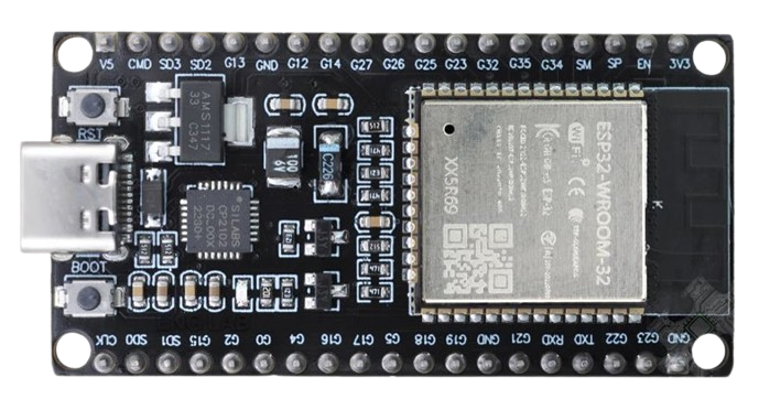
Pin Configuration and Descriptions
The ESP32 38P module has 38 pins, each with specific functions. Below is a summary of the pin configuration:
| Pin Number | Pin Name | Function |
|---|---|---|
| 1 | GND | Ground |
| 2 | 3V3 | 3.3V power output |
| 3 | EN | Enable pin (active high, used to reset the chip) |
| 4 | IO0 | GPIO0 (used for boot mode selection during programming) |
| 5-16 | IO1-IO12 | General-purpose input/output pins |
| 17 | IO13 | GPIO13 (supports PWM, ADC, etc.) |
| 18-25 | IO14-IO21 | General-purpose input/output pins |
| 26 | IO22 | GPIO22 (supports I2C, PWM, etc.) |
| 27-36 | IO23-IO32 | General-purpose input/output pins |
| 37 | RXD | UART receive pin |
| 38 | TXD | UART transmit pin |
Note: Some pins have multiple functions (e.g., ADC, DAC, PWM, I2C, SPI). Refer to the ESP32 datasheet for detailed pin multiplexing information.
Usage Instructions
How to Use the ESP32 38P Type-C CP2102 in a Circuit
Powering the Module:
- Connect the module to a computer or power source using a USB Type-C cable. The onboard voltage regulator will convert the 5V input to 3.3V for the ESP32.
- Alternatively, you can power the module directly via the 3V3 pin (ensure a stable 3.3V supply).
Programming the Module:
- Install the CP2102 USB-to-UART driver on your computer (available on the Espressif website or Silicon Labs).
- Use the Arduino IDE or Espressif's ESP-IDF to write and upload code to the ESP32. Select the appropriate board (e.g., "ESP32 Dev Module") in the IDE.
Connecting Peripherals:
- Use the GPIO pins to connect sensors, actuators, or other peripherals. Ensure that the voltage levels are compatible with the ESP32 (3.3V logic).
Boot Mode Selection:
- To upload code, hold the "BOOT" button while pressing the "EN" (reset) button. Release the "BOOT" button after the upload begins.
Important Considerations and Best Practices
- Voltage Levels: The ESP32 operates at 3.3V logic. Avoid connecting 5V signals directly to the GPIO pins to prevent damage.
- Power Supply: Ensure a stable power supply to avoid unexpected resets or malfunctions.
- Antenna Placement: For optimal Wi-Fi and Bluetooth performance, avoid placing metal objects near the onboard antenna.
- Heat Management: The ESP32 may generate heat during operation. Ensure proper ventilation if used in enclosed spaces.
Example Code for Arduino UNO Integration
Below is an example of how to use the ESP32 to control an LED via Wi-Fi:
#include <WiFi.h> // Include the Wi-Fi library

// Replace with your network credentials
const char* ssid = "Your_SSID";
const char* password = "Your_PASSWORD";

void setup() {
  Serial.begin(115200); // Initialize serial communication
  pinMode(2, OUTPUT);   // Set GPIO2 as an output pin (connected to an LED)

  // Connect to Wi-Fi
  Serial.print("Connecting to Wi-Fi");
  WiFi.begin(ssid, password);
  while (WiFi.status() != WL_CONNECTED) {
    delay(500);
    Serial.print(".");
  }
  Serial.println("\nWi-Fi connected!");
}

void loop() {
  digitalWrite(2, HIGH); // Turn the LED on
  delay(1000);           // Wait for 1 second
  digitalWrite(2, LOW);  // Turn the LED off
  delay(1000);           // Wait for 1 second
}
Note: Replace
Your_SSIDandYour_PASSWORDwith your Wi-Fi network credentials.
Troubleshooting and FAQs
Common Issues and Solutions
ESP32 Not Detected by Computer:
- Ensure the CP2102 driver is installed correctly.
- Try a different USB cable (some cables are power-only and do not support data transfer).
Code Upload Fails:
- Check the selected board and COM port in the Arduino IDE.
- Hold the "BOOT" button while uploading the code.
Wi-Fi Connection Issues:
- Verify the SSID and password in your code.
- Ensure the router is within range and supports 2.4 GHz Wi-Fi (ESP32 does not support 5 GHz).
Random Resets or Instability:
- Check the power supply for stability.
- Avoid using GPIO pins that are reserved for specific functions (e.g., GPIO0, GPIO2).
FAQs
Q: Can I use the ESP32 38P with a 5V sensor?
A: Yes, but you will need a level shifter to convert the 5V signal to 3.3V.
Q: How do I reset the ESP32?
A: Press the "EN" button on the module to reset the ESP32.
Q: Can I use the ESP32 for Bluetooth audio applications?
A: Yes, the ESP32 supports Bluetooth audio streaming via the A2DP profile.
Q: What is the maximum Wi-Fi range of the ESP32?
A: The range depends on the environment but typically extends up to 100 meters in open spaces.
For additional support, refer to the official Espressif documentation or community forums.