Cirkit Designer Logo
Cirkit Designer
Your all-in-one circuit design IDE
Home / 
Component Documentation

How to Use Resettable Fuse PTC: Examples, Pinouts, and Specs

Image of Resettable Fuse PTC
Cirkit Designer LogoDesign with Resettable Fuse PTC in Cirkit Designer

Introduction

A Resettable Fuse PTC (Positive Temperature Coefficient) is a protective electronic component designed to limit the flow of excessive current in a circuit. Unlike traditional fuses, which must be replaced after a single use, a PTC fuse automatically resets after the overcurrent condition has been cleared and the unit cools down. This makes them ideal for a wide range of applications where overcurrent protection is necessary but manual resetting or replacement of fuses is impractical or undesirable.

Explore Projects Built with Resettable Fuse PTC

Use Cirkit Designer to design, explore, and prototype these projects online. Some projects support real-time simulation. Click "Open Project" to start designing instantly!
PT100 Temperature Sensor with Rocker Switch and Resettable Fuse
Image of soldering iron: A project utilizing Resettable Fuse PTC in a practical application
This circuit is a basic power control system that uses a rocker switch to control the flow of 220V power through a resettable fuse and a PT100 temperature sensor. The switch allows the user to turn the power on or off, while the fuse provides overcurrent protection and the PT100 sensor can be used for temperature monitoring.
Cirkit Designer LogoOpen Project in Cirkit Designer
Basic Surge Protection Circuit with Benedict Switch
Image of DC & Monitoring Box: A project utilizing Resettable Fuse PTC in a practical application
The circuit includes a Benedict Switch connected in series with a Fuse Holder and an SPD (Surge Protection Device). The SPD is also connected to a Ground reference. This configuration suggests that the circuit is designed to control power flow, protect against overcurrent with the fuse, and guard against voltage surges with the SPD, with a safe path to ground for surge dissipation.
Cirkit Designer LogoOpen Project in Cirkit Designer
PID Temperature Control System with Thermocouple and SSR
Image of IR: A project utilizing Resettable Fuse PTC in a practical application
This circuit is a temperature control system that uses a thermocouple to measure temperature and a PID controller to regulate it. The PID controller drives a solid-state relay (SSR) to control an external load, with power supplied through an AC inlet socket.
Cirkit Designer LogoOpen Project in Cirkit Designer
Arduino Mega 2560 Controlled Relay Switch for PTC Air Heater
Image of ptc air heater functional test: A project utilizing Resettable Fuse PTC in a practical application
This circuit features an Arduino Mega 2560 microcontroller connected to a 4x4 membrane matrix keypad and a 1-channel relay module. The Arduino is programmed to interact with the keypad inputs and control the relay, which switches an AC supply connected to a PTC air heater. The purpose of the circuit is likely to allow user input via the keypad to control the heating element, potentially for a temperature regulation system.
Cirkit Designer LogoOpen Project in Cirkit Designer

Explore Projects Built with Resettable Fuse PTC

Use Cirkit Designer to design, explore, and prototype these projects online. Some projects support real-time simulation. Click "Open Project" to start designing instantly!
Image of soldering iron: A project utilizing Resettable Fuse PTC in a practical application
PT100 Temperature Sensor with Rocker Switch and Resettable Fuse
This circuit is a basic power control system that uses a rocker switch to control the flow of 220V power through a resettable fuse and a PT100 temperature sensor. The switch allows the user to turn the power on or off, while the fuse provides overcurrent protection and the PT100 sensor can be used for temperature monitoring.
Cirkit Designer LogoOpen Project in Cirkit Designer
Image of DC & Monitoring Box: A project utilizing Resettable Fuse PTC in a practical application
Basic Surge Protection Circuit with Benedict Switch
The circuit includes a Benedict Switch connected in series with a Fuse Holder and an SPD (Surge Protection Device). The SPD is also connected to a Ground reference. This configuration suggests that the circuit is designed to control power flow, protect against overcurrent with the fuse, and guard against voltage surges with the SPD, with a safe path to ground for surge dissipation.
Cirkit Designer LogoOpen Project in Cirkit Designer
Image of IR: A project utilizing Resettable Fuse PTC in a practical application
PID Temperature Control System with Thermocouple and SSR
This circuit is a temperature control system that uses a thermocouple to measure temperature and a PID controller to regulate it. The PID controller drives a solid-state relay (SSR) to control an external load, with power supplied through an AC inlet socket.
Cirkit Designer LogoOpen Project in Cirkit Designer
Image of ptc air heater functional test: A project utilizing Resettable Fuse PTC in a practical application
Arduino Mega 2560 Controlled Relay Switch for PTC Air Heater
This circuit features an Arduino Mega 2560 microcontroller connected to a 4x4 membrane matrix keypad and a 1-channel relay module. The Arduino is programmed to interact with the keypad inputs and control the relay, which switches an AC supply connected to a PTC air heater. The purpose of the circuit is likely to allow user input via the keypad to control the heating element, potentially for a temperature regulation system.
Cirkit Designer LogoOpen Project in Cirkit Designer

Common Applications and Use Cases

  • Overcurrent protection in consumer electronics (e.g., smartphones, laptops)
  • Protection for battery packs and chargers
  • Automotive electronics
  • Power supplies
  • Medical devices

Technical Specifications

Key Technical Details

  • Voltage Rating: The maximum voltage the PTC can withstand without damage.
  • Current Rating: The nominal operating current before the PTC trips.
  • Trip Current: The current at which the PTC will trip and increase its resistance.
  • Maximum Interrupt Current: The maximum fault current the PTC can withstand without damage.
  • Time to Trip: The time it takes for the PTC to trip at a specified multiple of its rated current.
  • Resistance: The initial resistance of the PTC before tripping and the resistance after tripping.

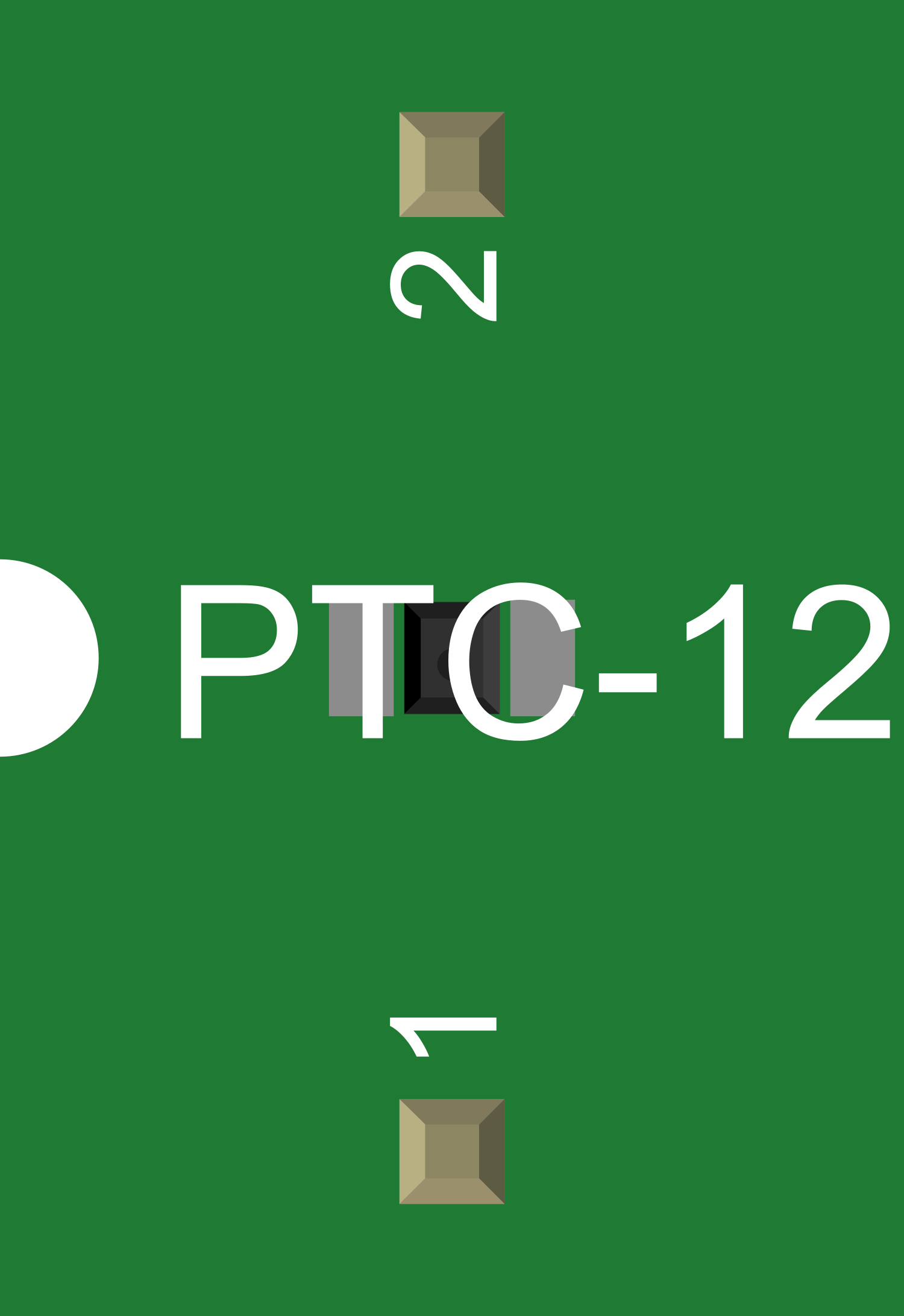
Pin Configuration and Descriptions

Pin Number Description
1 Current Input
2 Current Output

Note: The PTC is a two-terminal device, with the current flowing from pin 1 to pin 2.

Usage Instructions

How to Use the Component in a Circuit

  1. Identify the Correct PTC: Select a PTC with a voltage rating above the maximum circuit voltage and a current rating that matches the normal operating current of the circuit.
  2. Circuit Placement: Place the PTC in series with the load that needs protection.
  3. Soldering: Solder the PTC to the PCB with care to avoid excessive heat, which could trip the PTC prematurely.

Important Considerations and Best Practices

  • Selecting PTC: Ensure the trip current of the PTC is above the normal operating current but below the current that could damage the circuit.
  • Thermal Considerations: Be aware of the thermal environment as PTCs can trip due to ambient temperature increases.
  • Recovery Time: After tripping, allow time for the PTC to cool down and reset before resuming normal operation.
  • Testing: Test the PTC in the actual circuit to ensure it trips at the appropriate current levels.

Troubleshooting and FAQs

Common Issues Users Might Face

  • PTC Does Not Reset: If the PTC does not reset after tripping, check if the overcurrent condition still exists or if the ambient temperature is too high.
  • Nuisance Tripping: If the PTC trips during normal operation, it may be incorrectly specified. Check the trip current and ambient temperature conditions.

Solutions and Tips for Troubleshooting

  • Persistent Overcurrent: Investigate the circuit for faults or short circuits that may cause continuous overcurrent conditions.
  • Ambient Temperature: Ensure the PTC is operating within its specified temperature range.
  • Proper Sizing: Verify that the PTC is correctly sized for both the operating current and the maximum fault current of the circuit.

FAQs

Q: Can a PTC be used multiple times? A: Yes, a PTC is designed to reset itself after cooling down, allowing for multiple uses.

Q: How quickly does a PTC reset? A: The reset time can vary based on the PTC's design and the severity of the overcurrent condition. It can range from a few seconds to several minutes.

Q: Is a PTC the same as a thermistor? A: While both PTCs and thermistors have temperature-dependent resistance, a PTC is specifically designed to protect against overcurrent, while thermistors are generally used for temperature sensing.

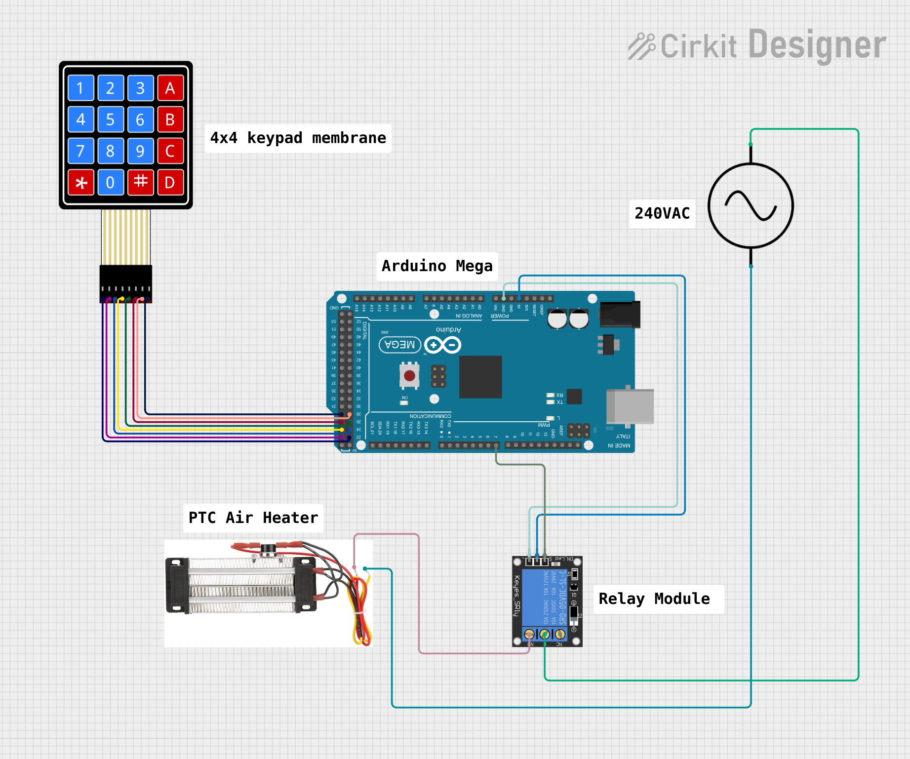
Q: Can I use a PTC with an Arduino UNO? A: Yes, a PTC can be used in circuits involving an Arduino UNO for overcurrent protection.

Example Code for Arduino UNO

// Example code to demonstrate the use of a PTC with an Arduino UNO
// This code does not directly interact with the PTC but shows a typical setup.

void setup() {
  pinMode(LED_BUILTIN, OUTPUT); // Set the built-in LED as an output
}

void loop() {
  digitalWrite(LED_BUILTIN, HIGH); // Turn on the LED
  delay(1000);                     // Wait for 1 second
  digitalWrite(LED_BUILTIN, LOW);  // Turn off the LED
  delay(1000);                     // Wait for 1 second
}

// Note: The PTC would be placed in series with the LED or other components
// to protect against overcurrent. The code itself does not control the PTC.

Remember to keep the PTC's specifications in mind when designing circuits with the Arduino UNO to ensure proper protection.