How to Use SparkFun Accessories LIDAR-Lite v3: Examples, Pinouts, and Specs
Introduction
The SparkFun Accessories LIDAR-Lite v3 (SEN-14032) is a compact, high-performance optical distance measurement sensor that utilizes laser-based time-of-flight technology to measure distances accurately. It is capable of measuring distances up to 40 meters with high precision, which makes it an ideal choice for a variety of applications including robotics, unmanned aerial vehicles (UAVs), and general distance sensing.
Explore Projects Built with SparkFun Accessories LIDAR-Lite v3
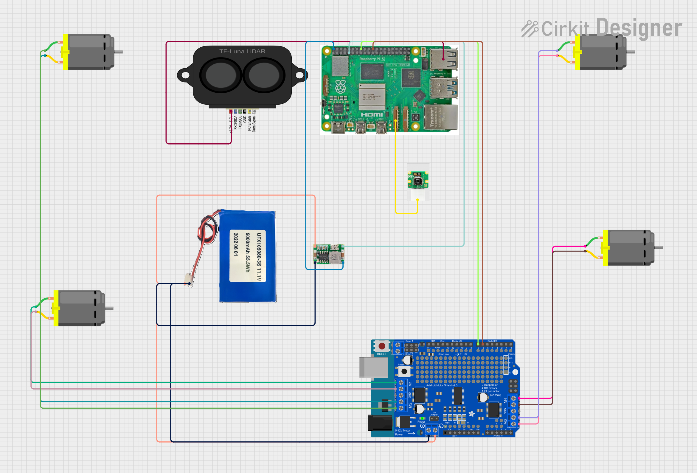

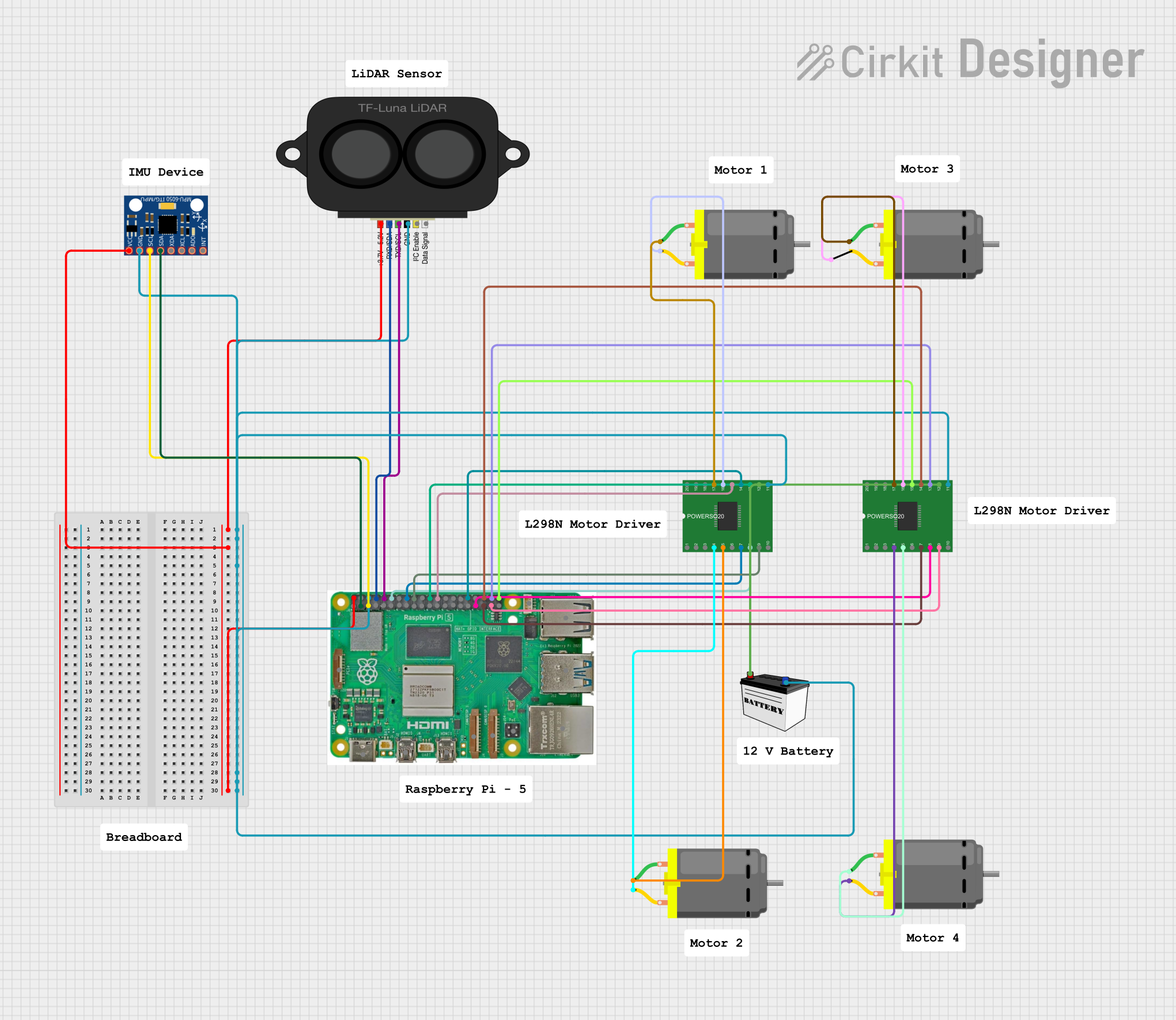
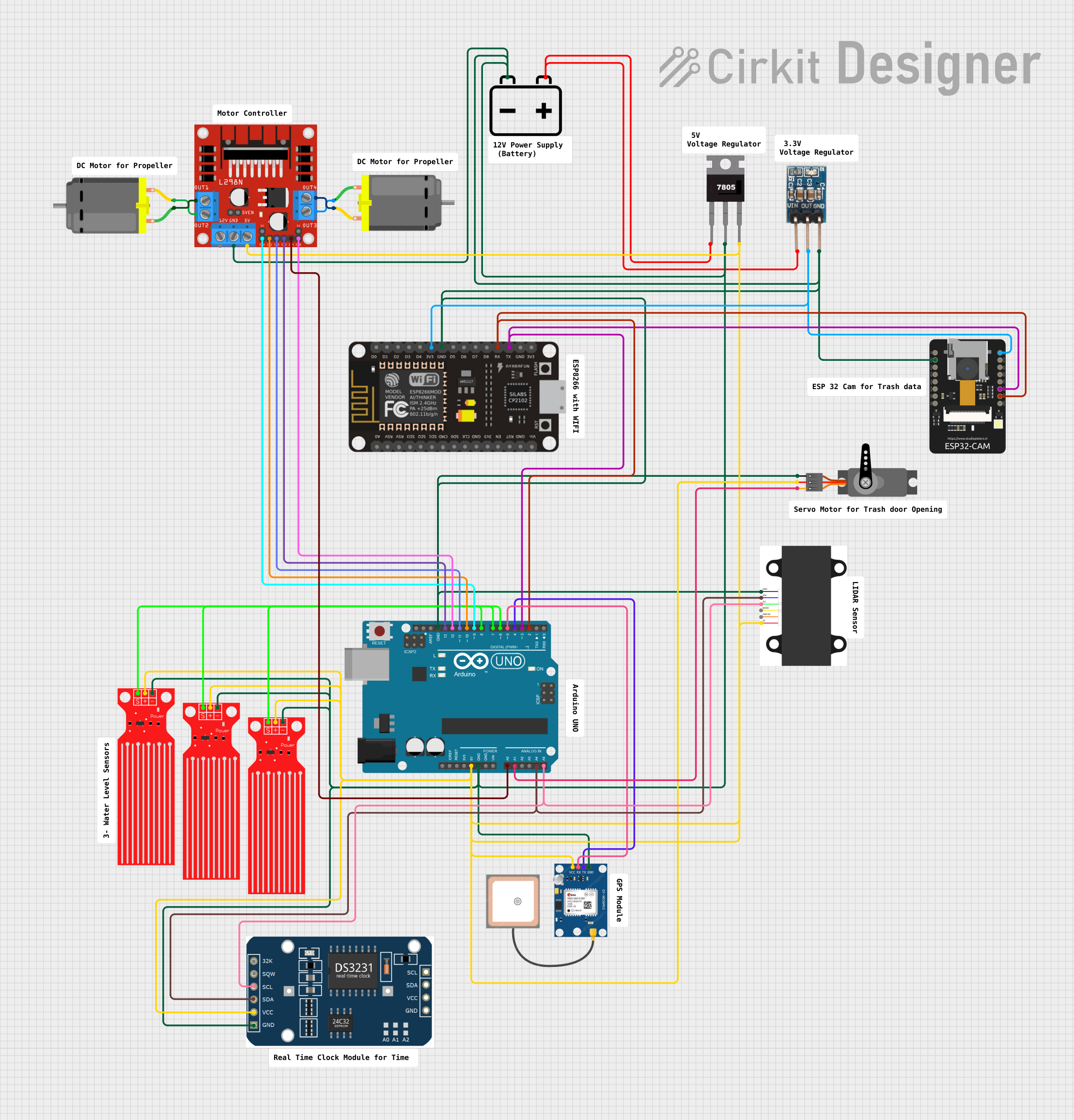
Explore Projects Built with SparkFun Accessories LIDAR-Lite v3
Common Applications and Use Cases
- Obstacle detection and avoidance for robotics
- UAV altitude and position control
- Level and volume measurement
- Security and surveillance systems
- Environmental scanning and 3D mapping
Technical Specifications
Key Technical Details
- Operating Voltage: 4.75 - 5 VDC
- Current Consumption: 105 mA during acquisition, 8 mA idle
- Range: 0 to 40 meters
- Resolution: 1 cm
- Accuracy: +/- 2.5 cm at distances greater than 1 meter
- Laser Class: Class 1
- Interface: I2C or PWM
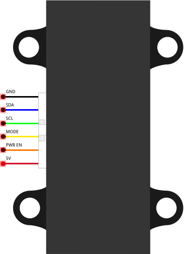
Pin Configuration and Descriptions
| Pin Number | Name | Description |
|---|---|---|
| 1 | +5V | Power supply input (4.75 - 5 VDC) |
| 2 | GND | Ground connection |
| 3 | SCL | I2C clock signal |
| 4 | SDA | I2C data signal |
| 5 | MODE | Mode control (PWM or I2C) |
| 6 | INT | Interrupt (LIDAR has made a distance measurement) |
Usage Instructions
How to Use the Component in a Circuit
- Power Supply: Connect the +5V and GND pins to a stable 5V power supply.
- I2C Communication: Connect the SCL and SDA pins to the corresponding I2C clock and data lines on your microcontroller.
- Mode Selection: The MODE pin can be left unconnected for default I2C operation or connected to GND for PWM mode.
- Interrupts (Optional): The INT pin can be connected to an interrupt-capable GPIO pin on your microcontroller to detect when a new measurement is available.
Important Considerations and Best Practices
- Ensure that the power supply is stable and within the specified voltage range.
- Avoid exposing the sensor to direct sunlight or other strong light sources that could interfere with the measurements.
- Keep the sensor's optical path clean and unobstructed.
- For accurate measurements, allow the sensor to warm up for a short period after powering on.
- Use proper I2C pull-up resistors if they are not already present on your microcontroller board.
Example Code for Arduino UNO
#include <Wire.h>

// LIDAR-Lite I2C address
const int LIDARLite_ADDRESS = 0x62;

// Function to read a two-byte value from a given register address
int readLIDARLite(int reg) {
  Wire.beginTransmission(LIDARLite_ADDRESS);
  Wire.write(reg); // Register to read from
  Wire.endTransmission();

  // Request 2 bytes from the sensor
  Wire.requestFrom(LIDARLite_ADDRESS, 2);
  if (Wire.available() >= 2) {
    int val = Wire.read() << 8; // Read high byte
    val |= Wire.read();         // Read low byte
    return val;
  }
  return 0; // Return 0 if no data available
}

void setup() {
  Wire.begin(); // Initialize I2C
  Serial.begin(9600); // Start serial communication at 9600 baud
}

void loop() {
  int distance = readLIDARLite(0x8f); // Read distance from LIDAR-Lite
  Serial.print("Distance: ");
  Serial.print(distance);
  Serial.println(" cm");
  delay(1000); // Wait for 1 second before next reading
}
Troubleshooting and FAQs
Common Issues Users Might Face
- Inaccurate Readings: Ensure there are no obstructions in front of the sensor and that the sensor is not facing highly reflective surfaces.
- No Data on I2C: Check the wiring, ensure proper pull-up resistors are in place, and verify that the correct I2C address is being used.
- Intermittent Operation: Make sure the power supply is stable and within the specified voltage range.
Solutions and Tips for Troubleshooting
- Power Issues: Use a multimeter to verify the voltage at the sensor's power input.
- Connection Issues: Double-check all connections and solder joints for continuity and proper contact.
- I2C Communication: Use an I2C scanner sketch to confirm that the sensor is detected on the I2C bus.
FAQs
Q: Can the LIDAR-Lite v3 be used outdoors? A: Yes, but it may be less effective in direct sunlight or adverse weather conditions.
Q: What is the maximum I2C bus speed for the LIDAR-Lite v3? A: The LIDAR-Lite v3 supports standard (100 kHz) and fast (400 kHz) I2C speeds.
Q: How can I increase the measurement rate? A: You can increase the measurement rate by reducing the acquisition time. Refer to the manufacturer's documentation for specific register settings.
Q: Is the LIDAR-Lite v3 compatible with 3.3V systems? A: While the sensor requires a 5V power supply, the I2C logic is 3.3V compatible with proper level shifting.
For further assistance, consult the manufacturer's detailed datasheet and user manual.