How to Use Encoder MA600: Examples, Pinouts, and Specs
Introduction
The Encoder MA600, manufactured by Monolithic Power Systems (MPS), is a high-performance rotary encoder designed to convert the angular position of a rotating shaft into an electrical signal. This component is widely used in applications requiring precise position feedback, such as industrial automation, robotics, motor control, and CNC machines. Its robust design and high accuracy make it suitable for demanding environments.
The MA600 is particularly valued for its compact size, low power consumption, and ability to deliver reliable performance in a variety of control systems.
Explore Projects Built with Encoder MA600
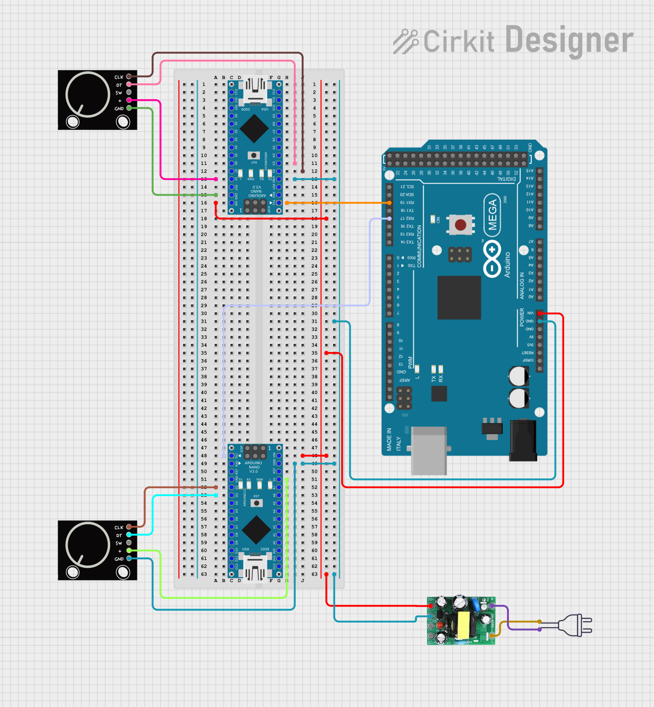

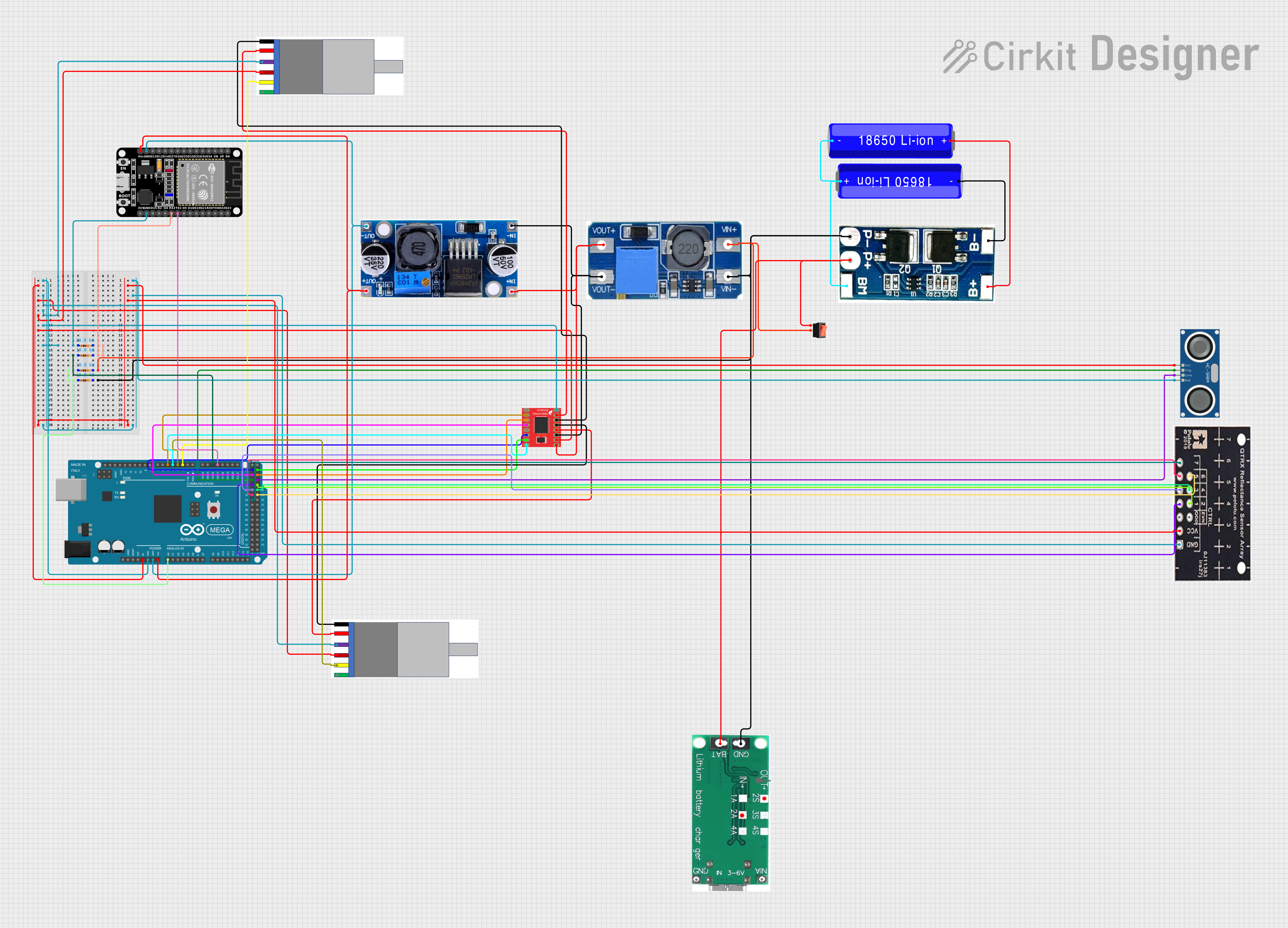
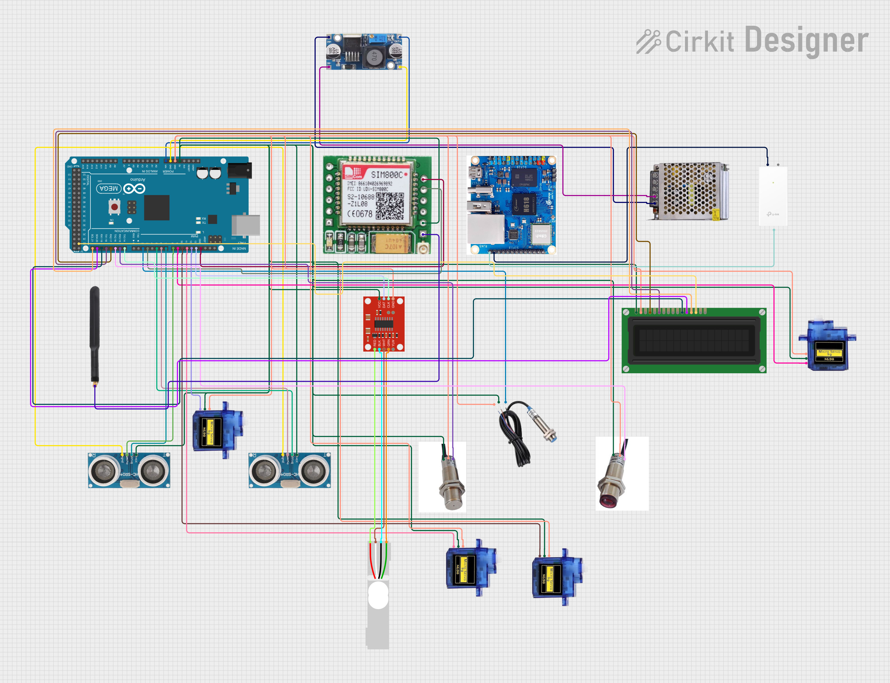
Explore Projects Built with Encoder MA600
Technical Specifications
Below are the key technical details of the Encoder MA600:
| Parameter | Value |
|---|---|
| Manufacturer | Monolithic Power Systems (MPS) |
| Part Number | MA600 |
| Operating Voltage | 3.3V to 5.5V |
| Maximum Current Consumption | 16mA (typical) |
| Resolution | Up to 12 bits (4096 positions per revolution) |
| Output Type | Digital (SPI, ABI, or PWM) |
| Maximum Rotational Speed | 60,000 RPM |
| Operating Temperature Range | -40°C to +125°C |
| Package Type | QFN-16 (3mm x 3mm) |
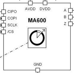
Pin Configuration and Descriptions
The MA600 comes in a 16-pin QFN package. Below is the pinout and description:
| Pin Number | Pin Name | Description |
|---|---|---|
| 1 | VDD | Power supply input (3.3V to 5.5V) |
| 2 | GND | Ground |
| 3 | SCK | SPI clock input |
| 4 | MISO | SPI data output |
| 5 | MOSI | SPI data input |
| 6 | CS | SPI chip select (active low) |
| 7 | ABI_A | Quadrature encoder output A |
| 8 | ABI_B | Quadrature encoder output B |
| 9 | ABI_I | Index pulse output |
| 10 | PWM | Pulse-width modulation output |
| 11 | NC | No connection |
| 12 | NC | No connection |
| 13 | TEST | Factory test pin (leave unconnected) |
| 14 | NC | No connection |
| 15 | NC | No connection |
| 16 | NC | No connection |
Usage Instructions
How to Use the Encoder MA600 in a Circuit
- Power Supply: Connect the VDD pin to a regulated 3.3V to 5.5V power source and the GND pin to the ground of your circuit.
- Communication Interface: Choose the desired output mode (SPI, ABI, or PWM) based on your application:
- For SPI communication, connect the SCK, MISO, MOSI, and CS pins to the corresponding pins on your microcontroller.
- For quadrature output, use the ABI_A, ABI_B, and ABI_I pins.
- For PWM output, connect the PWM pin to your microcontroller's input pin.
- Mounting: Secure the encoder to the rotating shaft using the recommended mechanical setup to ensure accurate position feedback.
- Initialization: If using SPI, configure the microcontroller to communicate with the MA600 at the appropriate clock speed (up to 10 MHz).
Important Considerations and Best Practices
- Magnet Alignment: The MA600 requires a diametrically magnetized magnet mounted on the rotating shaft. Ensure proper alignment for accurate readings.
- Decoupling Capacitor: Place a 0.1µF decoupling capacitor close to the VDD and GND pins to reduce noise.
- Signal Integrity: Use short and shielded wires for SPI communication to minimize noise and signal degradation.
- Temperature Range: Ensure the operating environment is within the specified temperature range (-40°C to +125°C).
Example Code for Arduino UNO
Below is an example of how to interface the MA600 with an Arduino UNO using SPI:
#include <SPI.h>

// Define SPI pins for the MA600
const int CS_PIN = 10; // Chip Select pin

void setup() {
  // Initialize serial communication for debugging
  Serial.begin(9600);

  // Set up SPI communication
  pinMode(CS_PIN, OUTPUT);
  digitalWrite(CS_PIN, HIGH); // Set CS pin high initially
  SPI.begin();
  SPI.setClockDivider(SPI_CLOCK_DIV16); // Set SPI clock speed
  SPI.setDataMode(SPI_MODE0); // SPI mode 0
}

void loop() {
  // Read data from the MA600
  digitalWrite(CS_PIN, LOW); // Select the MA600
  byte highByte = SPI.transfer(0x00); // Send dummy byte to receive high byte
  byte lowByte = SPI.transfer(0x00);  // Send dummy byte to receive low byte
  digitalWrite(CS_PIN, HIGH); // Deselect the MA600

  // Combine high and low bytes into a 16-bit value
  int position = (highByte << 8) | lowByte;

  // Print the position to the serial monitor
  Serial.print("Position: ");
  Serial.println(position);

  delay(100); // Wait 100ms before the next reading
}
Troubleshooting and FAQs
Common Issues and Solutions
No Output Signal:
- Ensure the power supply voltage is within the specified range (3.3V to 5.5V).
- Verify that the magnet is properly aligned with the encoder.
Inaccurate Position Readings:
- Check for mechanical misalignment of the magnet or shaft.
- Ensure the decoupling capacitor is installed near the VDD and GND pins.
SPI Communication Fails:
- Verify the SPI connections and ensure the correct SPI mode (Mode 0) is configured.
- Check the clock speed and reduce it if necessary to improve signal integrity.
Noise in Output Signals:
- Use shielded cables for signal lines and ensure proper grounding.
- Add filtering capacitors to reduce noise.
FAQs
Q: Can the MA600 be used in high-speed applications?
A: Yes, the MA600 supports rotational speeds of up to 60,000 RPM, making it suitable for high-speed applications.
Q: What type of magnet is required for the MA600?
A: A diametrically magnetized magnet is required for accurate position sensing.
Q: Can the MA600 output both SPI and quadrature signals simultaneously?
A: No, the output mode must be configured for either SPI, ABI (quadrature), or PWM, depending on the application.
Q: Is the MA600 suitable for outdoor use?
A: The MA600 is rated for a wide temperature range (-40°C to +125°C), but additional protection may be required for exposure to moisture or dust.