How to Use MCB TOMZN tob1z 63 c40 MCB PV: Examples, Pinouts, and Specs
Introduction
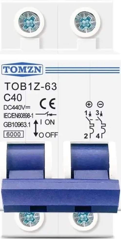
The TOMZN TOB1Z 63 C40 MCB is a miniature circuit breaker (MCB) specifically designed for photovoltaic (PV) applications. It is rated for a maximum current of 63A and features a C40 tripping characteristic, making it ideal for protecting solar power systems from overcurrent conditions. This MCB ensures safe and reliable operation by interrupting the circuit during overloads or short circuits, preventing damage to connected equipment and wiring.
Explore Projects Built with MCB TOMZN tob1z 63 c40 MCB PV
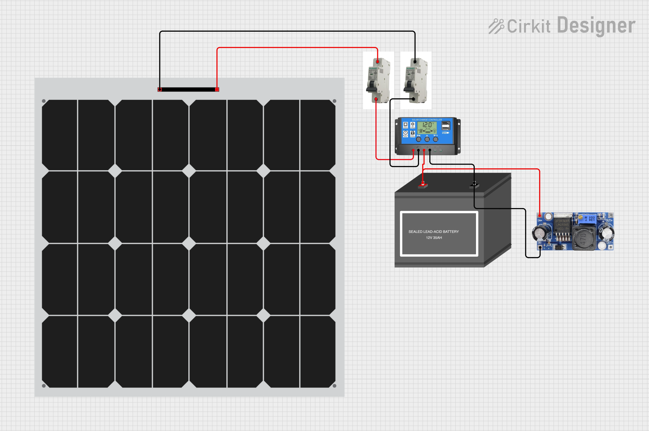
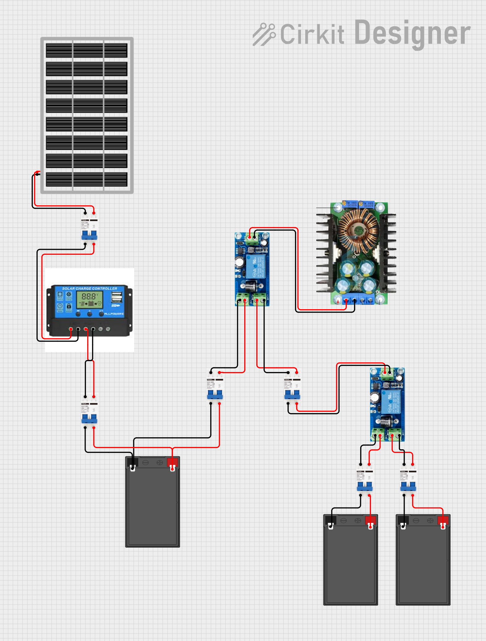


Explore Projects Built with MCB TOMZN tob1z 63 c40 MCB PV
Common Applications and Use Cases
- Overcurrent protection in photovoltaic (solar) systems
- DC circuit protection in renewable energy installations
- Residential and commercial solar panel arrays
- Battery storage systems in off-grid or hybrid setups
- Protection of inverters and other sensitive solar equipment
Technical Specifications
Key Technical Details
| Parameter | Value |
|---|---|
| Rated Current (In) | 63A |
| Tripping Characteristic | C40 |
| Rated Voltage (Un) | 1000V DC |
| Number of Poles | 2P (Double Pole) |
| Breaking Capacity | 6kA |
| Application | Photovoltaic (PV) systems |
| Operating Temperature | -25°C to +70°C |
| Mounting Type | DIN Rail (Standard 35mm) |
| Standards Compliance | IEC/EN 60947-2, IEC/EN 60898-1 |
Pin Configuration and Descriptions
The TOMZN TOB1Z 63 C40 MCB has a simple terminal configuration for connecting to DC circuits. Below is a description of the terminals:
| Terminal Label | Description |
|---|---|
| Line (+) | Positive input terminal from the DC source (e.g., solar panels) |
| Line (-) | Negative input terminal from the DC source |
| Load (+) | Positive output terminal to the load (e.g., inverter) |
| Load (-) | Negative output terminal to the load |
Usage Instructions
How to Use the Component in a Circuit
- Mounting the MCB: Securely install the MCB on a standard 35mm DIN rail in your distribution box or enclosure.
- Wiring:
- Connect the positive and negative terminals of the DC source (e.g., solar panels) to the
Line (+)andLine (-)terminals of the MCB. - Connect the
Load (+)andLoad (-)terminals to the input of the load (e.g., inverter or battery system). - Ensure all connections are tight and secure to prevent arcing or loose contacts.
- Connect the positive and negative terminals of the DC source (e.g., solar panels) to the
- Testing:
- After installation, switch on the MCB and verify that the circuit operates correctly.
- Test the tripping mechanism by simulating an overcurrent condition (if safe to do so) to ensure proper functionality.
Important Considerations and Best Practices
- Polarity: Always ensure correct polarity when connecting the MCB to avoid damage to the device or connected equipment.
- Voltage Rating: Do not exceed the rated voltage of 1000V DC to prevent insulation breakdown or failure.
- Current Rating: Ensure the connected load does not exceed the rated current of 63A.
- Environmental Conditions: Install the MCB in a dry, well-ventilated area, and avoid exposure to extreme temperatures or moisture.
- Periodic Maintenance: Regularly inspect the MCB for signs of wear, damage, or loose connections.
Arduino Integration
While the TOMZN TOB1Z 63 C40 MCB is not directly interfaced with microcontrollers like Arduino, it can be used in circuits that include Arduino-based solar monitoring systems. For example, you can use an Arduino to monitor the voltage and current of the solar system protected by this MCB.
Here is an example Arduino code snippet for monitoring voltage and current in a solar system:
// Example code for monitoring voltage and current in a solar system
// using an Arduino and sensors like a voltage divider and current sensor.

const int voltagePin = A0; // Analog pin for voltage sensor
const int currentPin = A1; // Analog pin for current sensor

float voltage = 0.0; // Variable to store measured voltage
float current = 0.0; // Variable to store measured current

void setup() {
  Serial.begin(9600); // Initialize serial communication
  // Print a message to indicate the system is starting
  Serial.println("Solar System Monitoring Started");
}

void loop() {
  // Read voltage and current sensor values
  int voltageRaw = analogRead(voltagePin);
  int currentRaw = analogRead(currentPin);

  // Convert raw values to actual voltage and current
  // Adjust the conversion factors based on your sensor specifications
  voltage = (voltageRaw / 1023.0) * 100.0; // Example: 0-100V range
  current = (currentRaw / 1023.0) * 50.0;  // Example: 0-50A range

  // Print the measured values to the Serial Monitor
  Serial.print("Voltage: ");
  Serial.print(voltage);
  Serial.println(" V");

  Serial.print("Current: ");
  Serial.print(current);
  Serial.println(" A");

  delay(1000); // Wait for 1 second before the next reading
}
Troubleshooting and FAQs
Common Issues and Solutions
MCB Does Not Trip During Overcurrent:
- Cause: Incorrect wiring or faulty MCB.
- Solution: Verify the wiring connections and ensure the MCB is installed correctly. Replace the MCB if it is defective.
Frequent Tripping:
- Cause: Overloaded circuit or short circuit in the system.
- Solution: Check the connected load to ensure it does not exceed the rated current of 63A. Inspect the circuit for any short circuits or faults.
Loose Connections:
- Cause: Improper tightening of terminal screws.
- Solution: Re-tighten all terminal screws and ensure secure connections.
MCB Overheating:
- Cause: High ambient temperature or poor ventilation.
- Solution: Install the MCB in a well-ventilated area and ensure it is not exposed to direct sunlight or heat sources.
FAQs
Can this MCB be used for AC circuits?
- No, the TOMZN TOB1Z 63 C40 MCB is specifically designed for DC circuits, particularly in photovoltaic applications.
What is the significance of the C40 tripping characteristic?
- The C40 characteristic means the MCB trips when the current exceeds 5 to 10 times the rated current (63A), making it suitable for circuits with moderate inrush currents, such as solar systems.
Is this MCB compatible with all solar panel setups?
- Yes, as long as the system voltage does not exceed 1000V DC and the current does not exceed 63A.
How often should the MCB be inspected?
- It is recommended to inspect the MCB every 6 to 12 months for signs of wear, damage, or loose connections.