How to Use Timer H3CR-A8: Examples, Pinouts, and Specs
Introduction
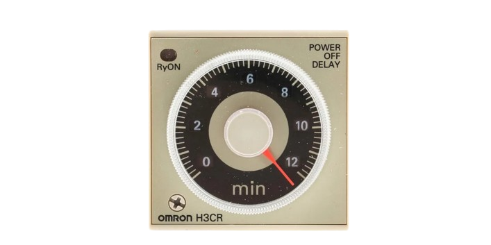
The Timer H3CR-A8, manufactured by Timer, is a versatile digital timer relay designed for precise control of timing functions in industrial and automation applications. This component is widely used in systems requiring delayed operations, interval timing, or cyclic control. Its robust design, multiple timing ranges, and user-friendly interface make it a reliable choice for a variety of use cases.
Explore Projects Built with Timer H3CR-A8


Explore Projects Built with Timer H3CR-A8
Common Applications
- Industrial automation systems
- Conveyor belt control
- Motor start/stop delay
- Lighting control systems
- Heating and cooling systems
- Sequential machine operations
Technical Specifications
Key Technical Details
| Parameter | Specification |
|---|---|
| Manufacturer | Timer |
| Part ID | H3CR-A8 |
| Power Supply Voltage | 100-240 VAC or 12-48 VDC |
| Timing Ranges | 0.05 seconds to 300 hours (selectable) |
| Output Type | SPDT (Single Pole Double Throw) relay |
| Contact Rating | 5A at 250 VAC (resistive load) |
| Operating Temperature | -10°C to +55°C |
| Storage Temperature | -25°C to +65°C |
| Mounting Style | Panel or DIN rail mount |
| Dimensions | 48 x 48 x 67 mm |
| Weight | Approximately 120 g |
Pin Configuration and Descriptions
The H3CR-A8 timer relay has a standard 8-pin configuration. Below is the pinout and description:
| Pin Number | Name | Description |
|---|---|---|
| 1 | A1 | Power supply input (AC/DC positive terminal) |
| 2 | A2 | Power supply input (AC/DC negative terminal) |
| 3 | 15 (COM) | Common terminal for relay output |
| 4 | 16 (NC) | Normally closed contact of the relay |
| 5 | 18 (NO) | Normally open contact of the relay |
| 6 | T1 | Timing input (used for external control) |
| 7 | T2 | Timing input (used for external control) |
| 8 | Not Used | Reserved (no connection) |
Usage Instructions
How to Use the Timer H3CR-A8 in a Circuit
Power Supply Connection:
- Connect the power supply to pins A1 and A2. Ensure the voltage matches the specified range (100-240 VAC or 12-48 VDC).
Relay Output Connection:
- Use pins 15 (COM), 16 (NC), and 18 (NO) to connect the load.
- For normally open operation, connect the load between COM and NO.
- For normally closed operation, connect the load between COM and NC.
Timing Configuration:
- Set the desired timing range using the rotary switches on the front panel.
- Adjust the fine timing knob to set the exact delay or interval.
External Control (Optional):
- If external control is required, connect the control signal to pins T1 and T2.
Mounting:
- Mount the timer on a DIN rail or panel as per your application requirements.
Important Considerations and Best Practices
- Ensure the power supply voltage is within the specified range to avoid damage.
- Use appropriate fuses or circuit breakers to protect the timer and connected devices.
- Avoid exposing the timer to excessive vibration, moisture, or extreme temperatures.
- For inductive loads (e.g., motors), use a snubber circuit or surge suppressor to protect the relay contacts.
- Regularly inspect the timer for signs of wear or damage, especially in high-duty-cycle applications.
Example: Connecting Timer H3CR-A8 to an Arduino UNO
The H3CR-A8 can be used with an Arduino UNO to control timing functions. Below is an example of how to interface the timer with an Arduino:
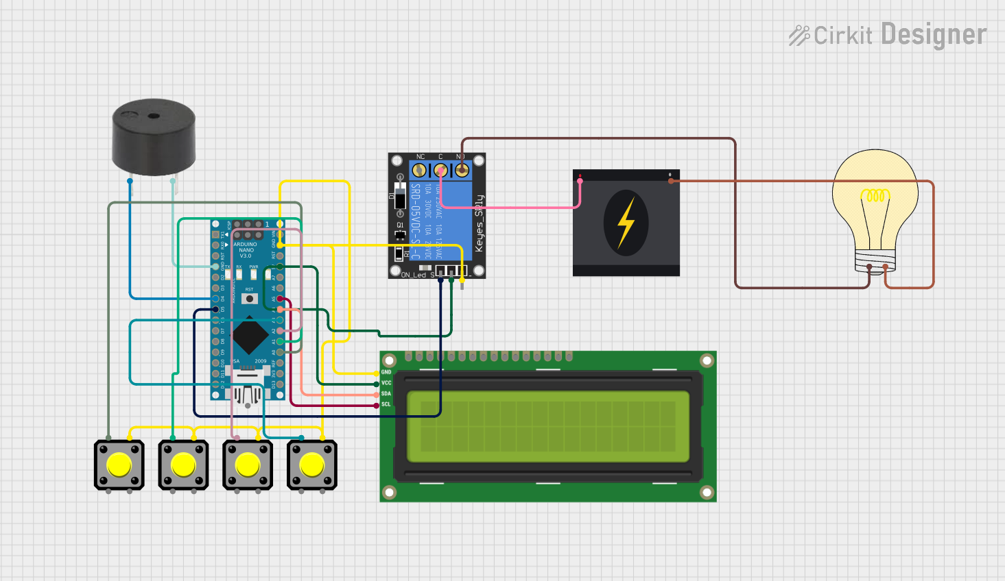
Circuit Description
- The Arduino controls the timer's external input (pins T1 and T2) to start or stop the timing operation.
- The relay output of the timer is used to control a load (e.g., an LED or motor).
Arduino Code
// Example code to control Timer H3CR-A8 using Arduino UNO
// Pin 7 is used to send a HIGH/LOW signal to the timer's T1 input

const int timerControlPin = 7; // Arduino pin connected to T1 of H3CR-A8
const int delayTime = 5000;    // Delay time in milliseconds (5 seconds)

void setup() {
  pinMode(timerControlPin, OUTPUT); // Set pin 7 as an output
  digitalWrite(timerControlPin, LOW); // Ensure the timer is initially off
}

void loop() {
  digitalWrite(timerControlPin, HIGH); // Start the timer
  delay(delayTime);                    // Wait for the delay time
  digitalWrite(timerControlPin, LOW);  // Stop the timer
  delay(2000);                         // Wait 2 seconds before restarting
}
Notes:
- Use a transistor or optocoupler if the Arduino cannot directly drive the timer's input.
- Ensure proper grounding between the Arduino and the timer.
Troubleshooting and FAQs
Common Issues and Solutions
| Issue | Possible Cause | Solution |
|---|---|---|
| Timer does not power on | Incorrect power supply connection | Verify connections to pins A1 and A2. |
| Relay does not activate | Incorrect wiring of relay output | Check connections to pins 15, 16, and 18. |
| Timing is inaccurate | Incorrect timing range or knob setting | Recheck and adjust the timing settings. |
| External control not working | Signal not reaching T1/T2 inputs | Verify the control signal and connections. |
| Timer overheats | Overloading of relay contacts | Ensure the load does not exceed 5A/250VAC. |
FAQs
Can the H3CR-A8 handle DC loads?
Yes, the relay can handle DC loads, but ensure the voltage and current ratings are within the specified limits.What happens if the power supply voltage fluctuates?
The timer is designed to tolerate minor fluctuations, but significant deviations may cause malfunction or damage.Can I use the H3CR-A8 for cyclic operations?
Yes, the timer supports cyclic timing modes. Refer to the user manual for detailed configuration.Is the timer suitable for outdoor use?
The H3CR-A8 is not weatherproof. Use it in a protected environment or an enclosure for outdoor applications.How do I reset the timer?
The timer resets automatically when the power is turned off or the control signal is removed.
By following this documentation, users can effectively integrate and troubleshoot the Timer H3CR-A8 in their projects.