How to Use Solar Panel Regulator 5A MPPT Controller Battery Charging 9V/12V/24V/Auto Switch: Examples, Pinouts, and Specs
Introduction
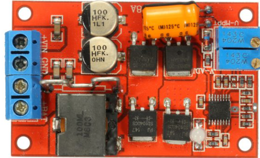
The Solar Panel Regulator 5A MPPT Controller is a device designed to optimize the power output from solar panels by employing Maximum Power Point Tracking (MPPT) technology. This advanced feature ensures that the solar panel operates at its most efficient point, maximizing energy harvest. The regulator is capable of charging batteries at multiple voltage levels (9V, 12V, 24V) and includes an automatic voltage switch for seamless operation. It is ideal for renewable energy systems, off-grid setups, and battery charging applications.
Explore Projects Built with Solar Panel Regulator 5A MPPT Controller Battery Charging 9V/12V/24V/Auto Switch
Explore Projects Built with Solar Panel Regulator 5A MPPT Controller Battery Charging 9V/12V/24V/Auto Switch
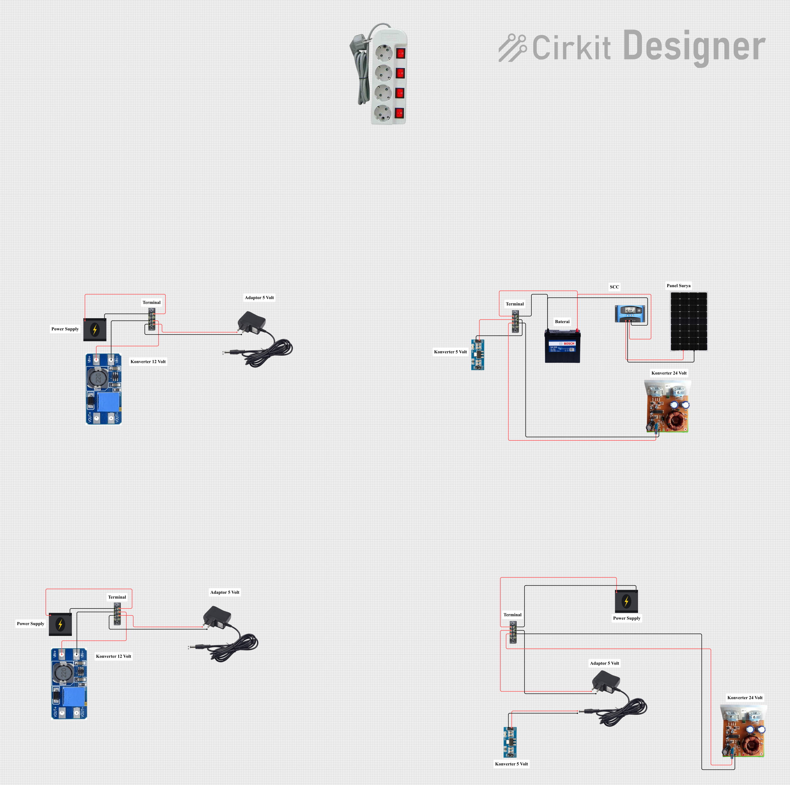
Common Applications
- Solar-powered battery charging systems
- Off-grid renewable energy installations
- RVs, boats, and camping setups
- Backup power systems
- Small-scale solar energy projects
Technical Specifications
Key Technical Details
- Input Voltage Range: 9V to 24V (from solar panel)
- Output Voltage Options: 9V, 12V, 24V (auto-switching)
- Maximum Current: 5A
- Technology: Maximum Power Point Tracking (MPPT)
- Efficiency: ≥ 95%
- Operating Temperature Range: -20°C to 60°C
- Battery Compatibility: Lead-acid, lithium-ion, and other rechargeable batteries
- Protection Features: Overcharge, overcurrent, short circuit, and reverse polarity protection
Pin Configuration and Descriptions
| Pin Name | Type | Description |
|---|---|---|
Solar+ |
Input (Positive) | Positive terminal for connecting the solar panel. |
Solar- |
Input (Negative) | Negative terminal for connecting the solar panel. |
Battery+ |
Output (Positive) | Positive terminal for connecting the battery to be charged. |
Battery- |
Output (Negative) | Negative terminal for connecting the battery to be charged. |
Load+ |
Output (Positive) | Positive terminal for connecting a load (optional, e.g., DC appliances). |
Load- |
Output (Negative) | Negative terminal for connecting a load (optional, e.g., DC appliances). |
Indicator LED |
Status Output | Built-in LED indicators for charging status, fault detection, and power level. |
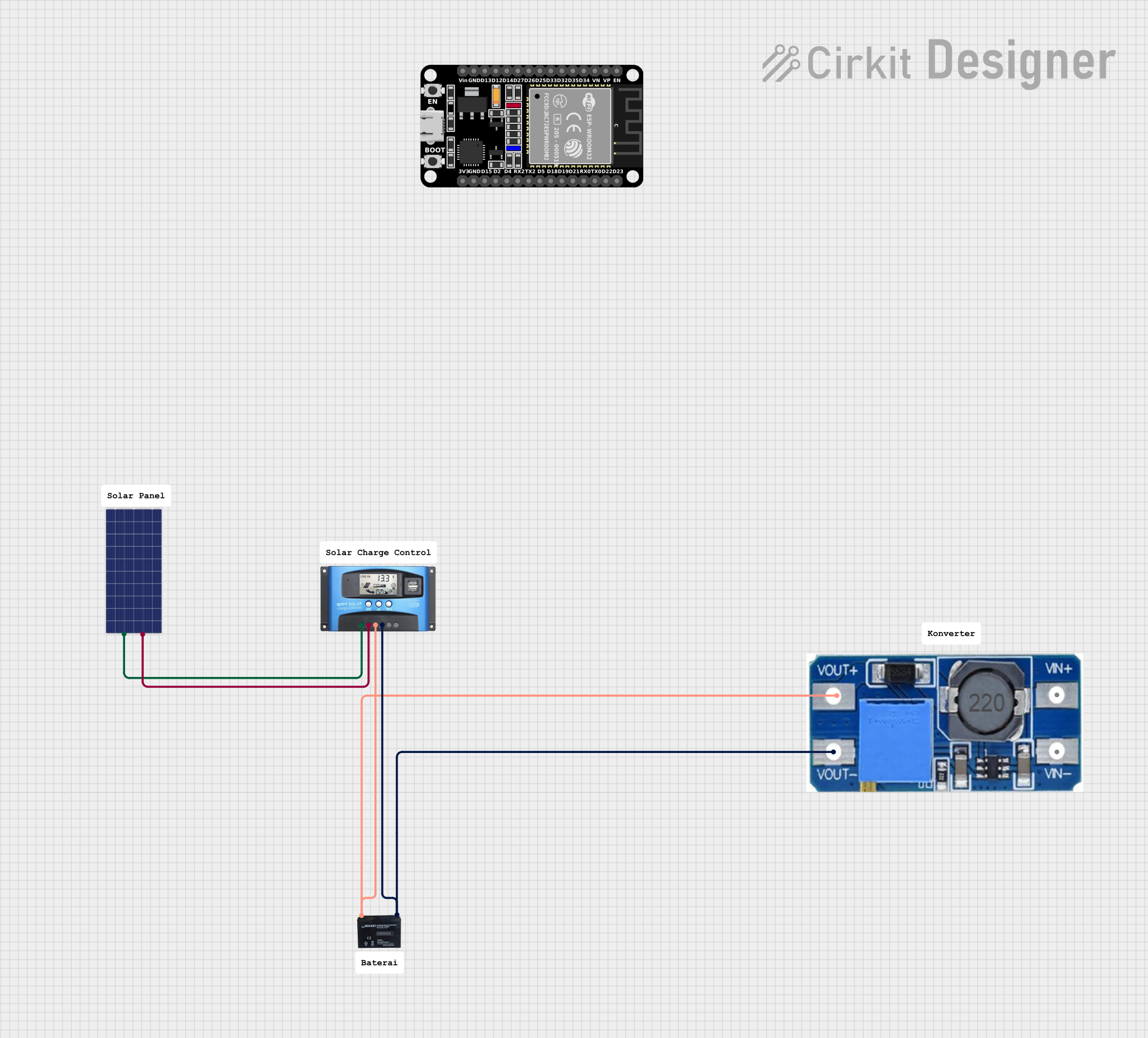
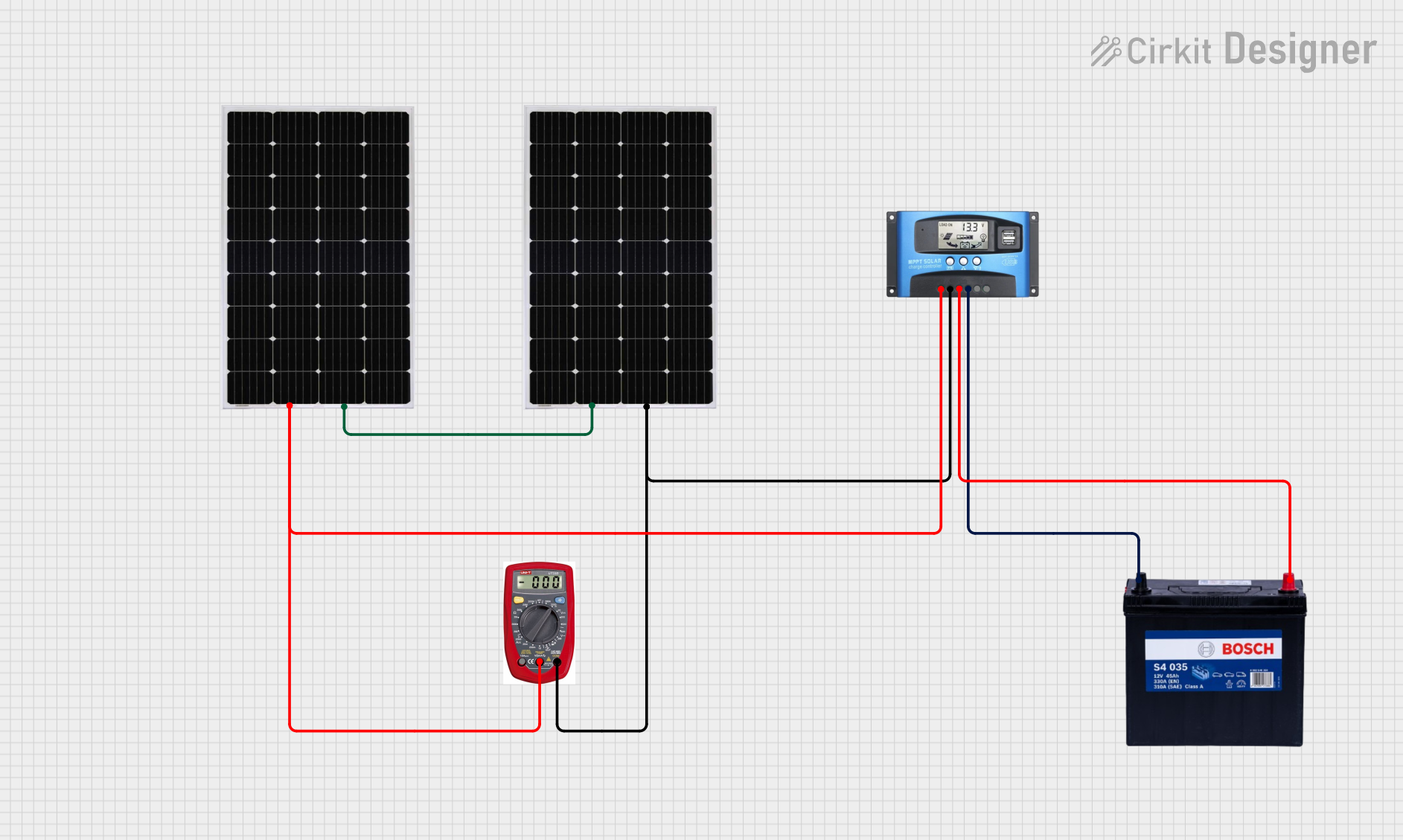
Usage Instructions
How to Use the Component in a Circuit
- Connect the Solar Panel:
- Attach the positive terminal of the solar panel to the
Solar+pin. - Attach the negative terminal of the solar panel to the
Solar-pin.
- Attach the positive terminal of the solar panel to the
- Connect the Battery:
- Connect the positive terminal of the battery to the
Battery+pin. - Connect the negative terminal of the battery to the
Battery-pin.
- Connect the positive terminal of the battery to the
- Optional Load Connection:
- If you wish to power a load directly, connect the load's positive terminal to the
Load+pin and the negative terminal to theLoad-pin.
- If you wish to power a load directly, connect the load's positive terminal to the
- Verify Connections:
- Double-check all connections to ensure proper polarity and secure wiring.
- Power On:
- Place the solar panel in sunlight. The MPPT controller will automatically detect the battery voltage and begin charging.
Important Considerations and Best Practices
- Ensure the solar panel's voltage and current ratings are within the regulator's input range.
- Use appropriately rated wires to handle the current (5A max) and minimize power loss.
- Place the regulator in a well-ventilated area to prevent overheating.
- Avoid exposing the regulator to water or extreme environmental conditions.
- Regularly check the battery's health to prevent overcharging or deep discharge.
Arduino UNO Integration Example
While the MPPT controller operates independently, you can monitor its performance using an Arduino UNO. For example, you can measure the battery voltage and display it on a serial monitor.
// Arduino code to monitor battery voltage from the MPPT controller
const int batteryPin = A0; // Analog pin connected to Battery+ via a voltage divider
float voltage = 0.0;

void setup() {
  Serial.begin(9600); // Initialize serial communication
}

void loop() {
  int sensorValue = analogRead(batteryPin); // Read analog value
  voltage = (sensorValue * 5.0 / 1023.0) * 2;
  // Convert to voltage (assuming a 2:1 voltage divider)

  Serial.print("Battery Voltage: ");
  Serial.print(voltage);
  Serial.println(" V");

  delay(1000); // Wait 1 second before next reading
}
Note: Use a voltage divider circuit to scale down the battery voltage to a safe range (0-5V) for the Arduino's analog input.
Troubleshooting and FAQs
Common Issues and Solutions
No Charging Detected:
- Cause: Incorrect wiring or insufficient sunlight.
- Solution: Verify all connections and ensure the solar panel is exposed to direct sunlight.
Overheating of the Regulator:
- Cause: Poor ventilation or excessive current draw.
- Solution: Place the regulator in a well-ventilated area and ensure the load does not exceed 5A.
Battery Not Charging Fully:
- Cause: Battery capacity mismatch or degraded battery.
- Solution: Check the battery's health and ensure it is compatible with the regulator.
LED Indicators Not Working:
- Cause: Faulty regulator or incorrect wiring.
- Solution: Inspect the wiring and replace the regulator if necessary.
FAQs
Q: Can I use this regulator with a 48V battery?
A: No, this regulator supports batteries with voltages of 9V, 12V, and 24V only.Q: Does the regulator work at night?
A: No, the regulator requires sunlight to generate power from the solar panel.Q: Can I connect multiple solar panels?
A: Yes, but ensure the combined voltage and current do not exceed the regulator's input limits.Q: How do I know if the MPPT is working?
A: The built-in LED indicators will show the charging status and fault conditions. Additionally, you can monitor the battery voltage to confirm charging activity.
This concludes the documentation for the Solar Panel Regulator 5A MPPT Controller.