How to Use SMPS: Examples, Pinouts, and Specs

 Design with SMPS in Cirkit Designer
Introduction
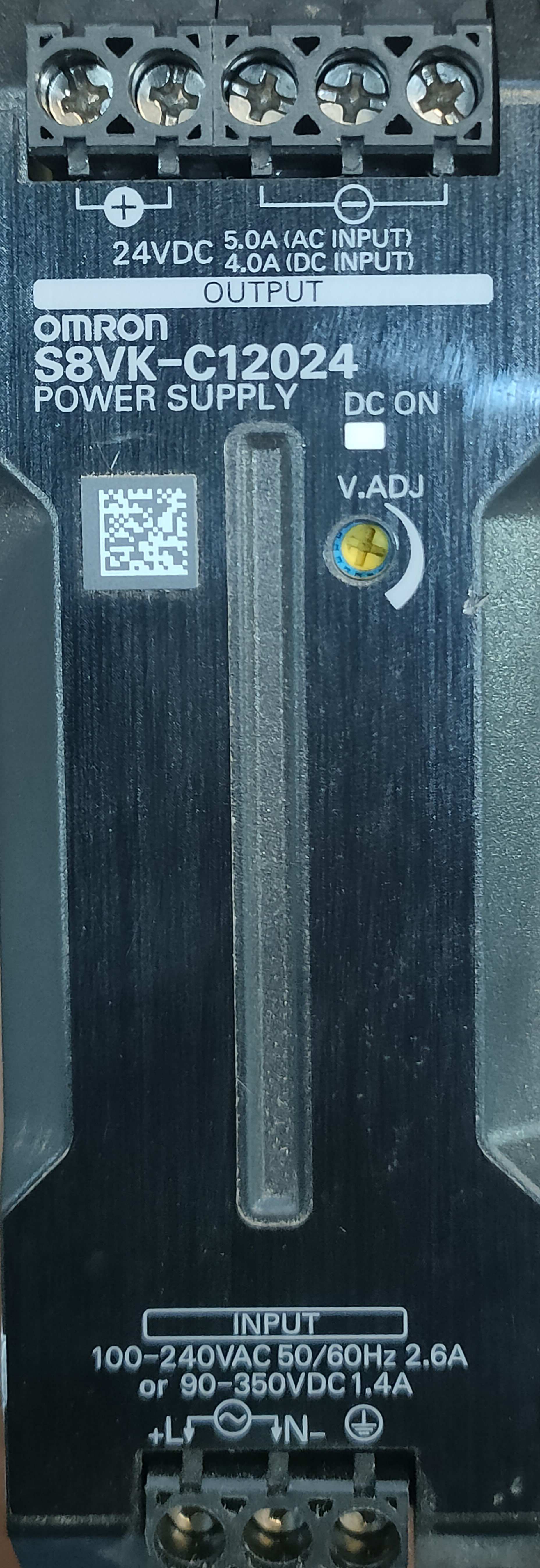
A Switch Mode Power Supply (SMPS) is an electronic power supply that utilizes a switching regulator to efficiently convert electrical power. Unlike linear power supplies, SMPS can step up, step down, or invert voltage levels, making it highly versatile. Its compact size, lightweight design, and high efficiency make it a popular choice in modern electronic devices.
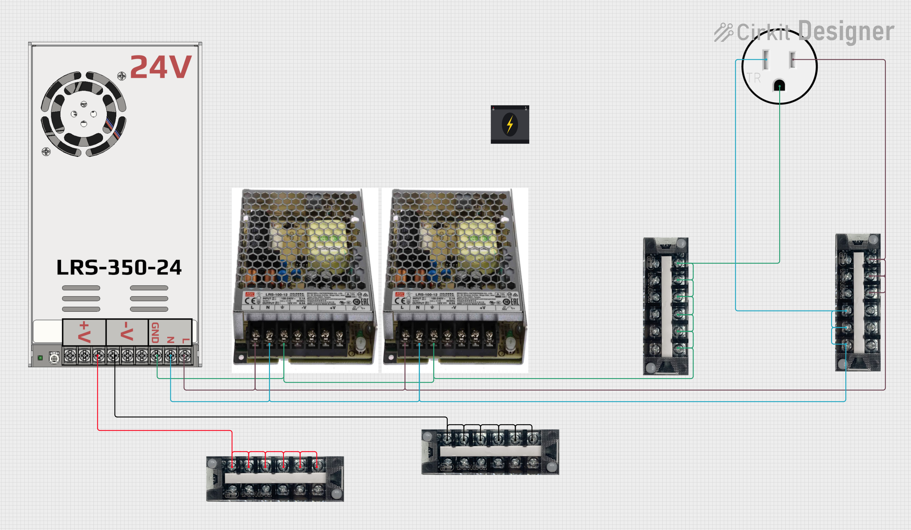
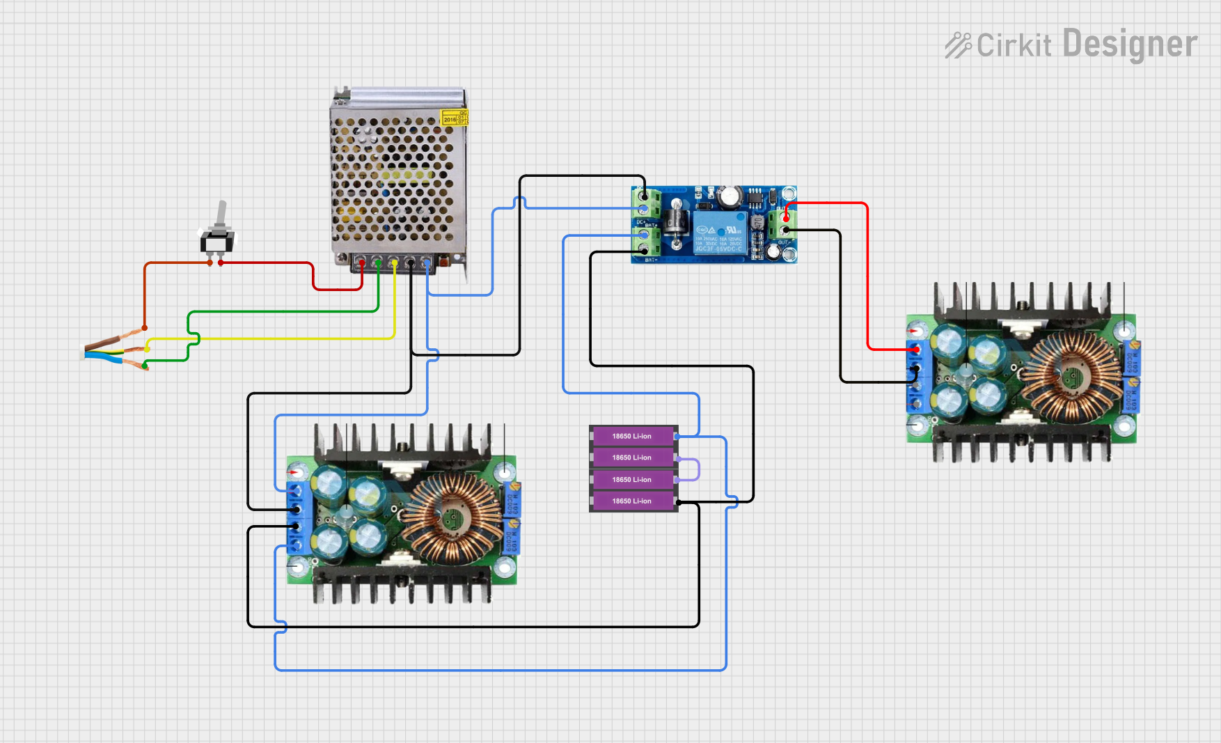
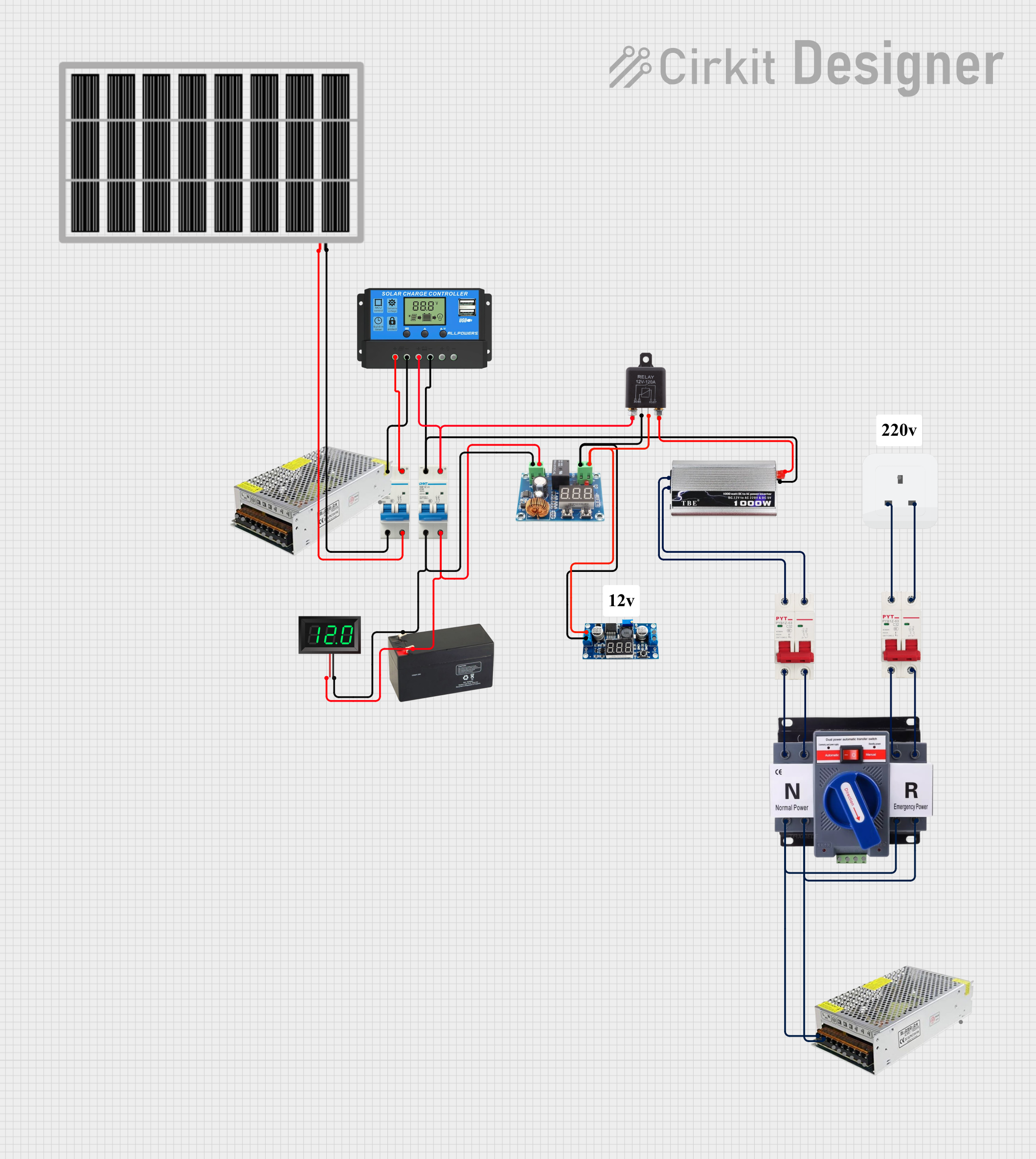
Explore Projects Built with SMPS

 Open Project in Cirkit Designer
 Open Project in Cirkit Designer
 Open Project in Cirkit Designer
 Open Project in Cirkit Designer
Explore Projects Built with SMPS

 Open Project in Cirkit Designer
 Open Project in Cirkit Designer
 Open Project in Cirkit Designer
 Open Project in Cirkit Designer
Common Applications and Use Cases
- Powering consumer electronics (e.g., TVs, computers, and mobile chargers)
- Industrial automation systems
- LED lighting systems
- Telecommunications equipment
- Battery charging circuits
- Renewable energy systems (e.g., solar inverters)
Technical Specifications
Below are the general technical specifications of a typical SMPS. Note that actual values may vary depending on the specific model and manufacturer.
Key Technical Details
- Input Voltage Range: 85V AC to 265V AC (universal input) or 12V DC to 48V DC
- Output Voltage Range: 3.3V DC to 48V DC (depending on the design)
- Output Current: 0.5A to 50A (varies by model)
- Efficiency: 80% to 95%
- Switching Frequency: 20 kHz to 1 MHz
- Ripple and Noise: Typically <1% of output voltage
- Operating Temperature: -20°C to +70°C
- Protection Features: Overvoltage, overcurrent, short-circuit, and thermal protection
Pin Configuration and Descriptions
The pin configuration of an SMPS depends on its type (AC-DC or DC-DC) and design. Below is a general example for a DC-DC SMPS module:
| Pin | Name | Description |
|---|---|---|
| 1 | VIN (+) | Positive input voltage terminal. Connect to the input power source. |
| 2 | GND (Input) | Ground terminal for the input power source. |
| 3 | VOUT (+) | Positive output voltage terminal. Connect to the load. |
| 4 | GND (Output) | Ground terminal for the output voltage. |
| 5 | EN (Enable) | Optional enable pin. High signal enables the SMPS; low signal disables it. |
| 6 | ADJ (Adjust) | Optional pin to adjust the output voltage (if supported by the module). |
Usage Instructions
How to Use the SMPS in a Circuit
Determine Input and Output Requirements:
- Verify the input voltage range of the SMPS matches your power source.
- Ensure the output voltage and current ratings meet the requirements of your load.
Connect the Input:
- Connect the positive terminal of the power source to the VIN (+) pin.
- Connect the ground terminal of the power source to the GND (Input) pin.
Connect the Output:
- Connect the positive terminal of the load to the VOUT (+) pin.
- Connect the ground terminal of the load to the GND (Output) pin.
Enable the SMPS (if applicable):
- If the SMPS has an enable pin, ensure it is connected to a high signal to activate the module.
Adjust the Output Voltage (if applicable):
- If the SMPS has an adjustable output, use the ADJ pin or onboard potentiometer to set the desired voltage.
Power On:
- Turn on the input power source and verify the output voltage using a multimeter.
Important Considerations and Best Practices
- Always check the polarity of the input and output connections to avoid damage.
- Use appropriate heat sinks or cooling mechanisms if the SMPS operates at high power levels.
- Ensure the input and output capacitors are rated for the voltage and current levels in your circuit.
- Avoid exceeding the maximum input voltage, output current, or power rating of the SMPS.
- Use proper filtering components (e.g., capacitors and inductors) to minimize noise and ripple.
Example: Using an SMPS with an Arduino UNO
Below is an example of connecting a 5V DC-DC SMPS to power an Arduino UNO:
Circuit Connections
- Connect the VIN (+) pin of the SMPS to a 12V DC power source.
- Connect the GND (Input) pin of the SMPS to the ground of the power source.
- Connect the VOUT (+) pin of the SMPS to the 5V pin of the Arduino UNO.
- Connect the GND (Output) pin of the SMPS to the GND pin of the Arduino UNO.
Sample Code
// Example code to blink an LED using Arduino UNO powered by an SMPS

const int ledPin = 13; // Pin connected to the onboard LED

void setup() {
  pinMode(ledPin, OUTPUT); // Set the LED pin as an output
}

void loop() {
  digitalWrite(ledPin, HIGH); // Turn the LED on
  delay(1000);                // Wait for 1 second
  digitalWrite(ledPin, LOW);  // Turn the LED off
  delay(1000);                // Wait for 1 second
}
Troubleshooting and FAQs
Common Issues and Solutions
No Output Voltage:
- Cause: Incorrect input connections or insufficient input voltage.
- Solution: Verify the input connections and ensure the input voltage is within the specified range.
Overheating:
- Cause: Excessive load or inadequate cooling.
- Solution: Reduce the load or add a heat sink/fan to improve cooling.
High Ripple or Noise:
- Cause: Insufficient filtering or poor grounding.
- Solution: Add external capacitors or inductors to filter the output. Ensure proper grounding.
Output Voltage Fluctuations:
- Cause: Load variations or unstable input voltage.
- Solution: Use a stable input power source and ensure the load is within the SMPS's rated capacity.
FAQs
Q: Can I use an SMPS to power sensitive electronics?
A: Yes, but ensure the SMPS has low ripple and noise. You can add additional filtering if needed.Q: How do I adjust the output voltage of an adjustable SMPS?
A: Use the onboard potentiometer or the ADJ pin (if available) to fine-tune the output voltage.Q: Can an SMPS be used with batteries?
A: Yes, as long as the input voltage is within the SMPS's specified range.Q: What happens if I exceed the maximum load current?
A: The SMPS may shut down, enter protection mode, or overheat. Always stay within the rated current.
This concludes the documentation for the SMPS. Follow the guidelines above to ensure safe and efficient operation of your SMPS module.