
How to Use Bridge Load sensor: Examples, Pinouts, and Specs
 Design with Bridge Load sensor in Cirkit Designer
Introduction
A Bridge Load Sensor is a type of transducer designed to measure the load or weight applied to it. It operates by converting mechanical force into an electrical signal, typically using a Wheatstone bridge configuration. This component is widely used in applications such as digital weighing scales, industrial force measurement systems, and structural health monitoring. Its high precision and reliability make it an essential component in systems requiring accurate force or weight measurements.
Explore Projects Built with Bridge Load sensor
 Open Project in Cirkit Designer
 Open Project in Cirkit Designer
 Open Project in Cirkit Designer
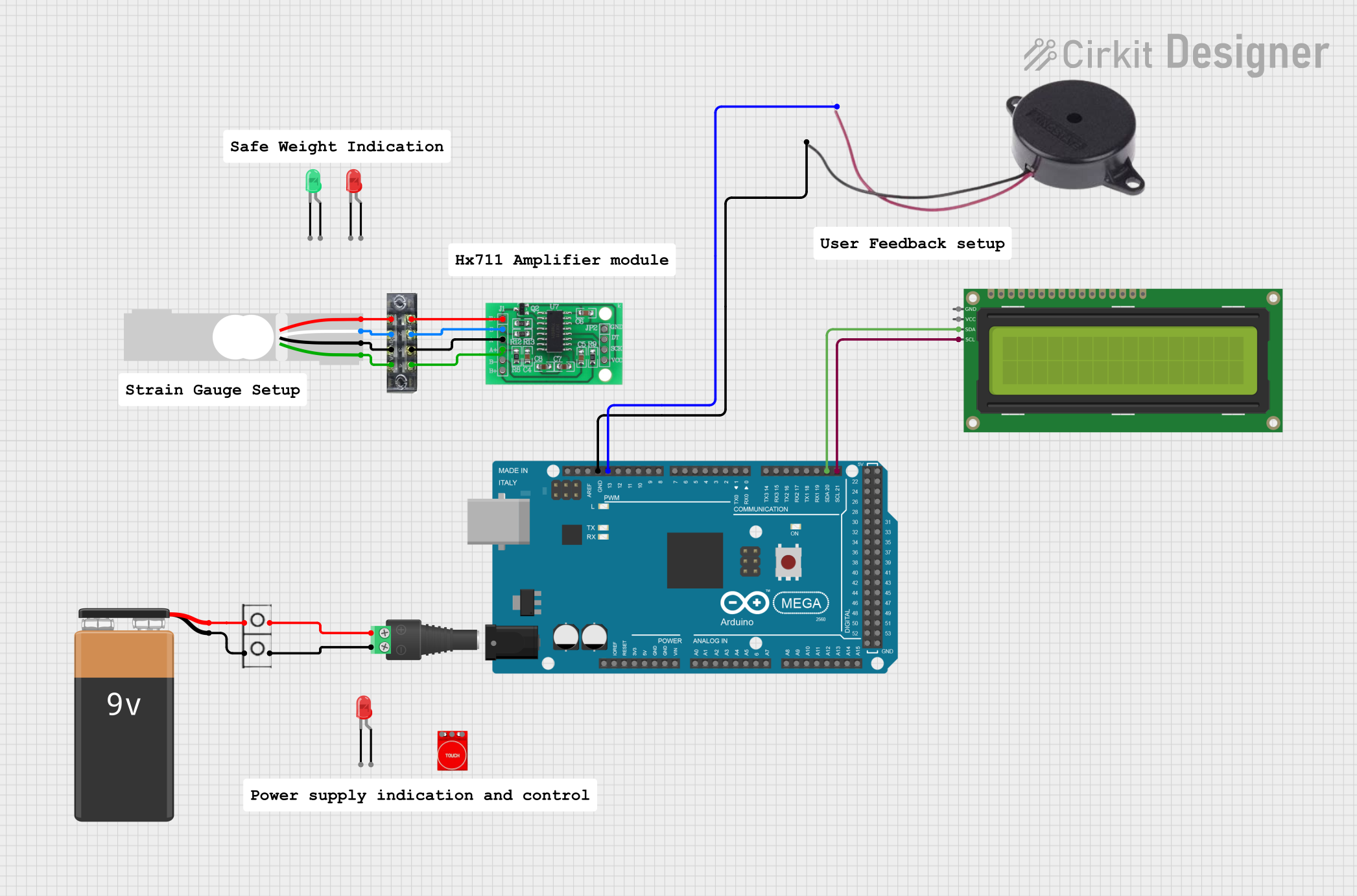 Open Project in Cirkit Designer
Explore Projects Built with Bridge Load sensor
Open Project in Cirkit DesignerOpen Project in Cirkit DesignerOpen Project in Cirkit DesignerOpen Project in Cirkit DesignerTechnical Specifications
- Type: Strain gauge-based load sensor
- Operating Voltage: 5V DC (typical)
- Output Signal: Millivolt range (requires amplification)
- Load Capacity: Varies by model (e.g., 5kg, 10kg, 50kg, etc.)
- Accuracy: ±0.03% of full scale (typical)
- Temperature Range: -10°C to 50°C
- Material: Aluminum alloy or stainless steel (depending on model)
- Configuration: Full-bridge Wheatstone bridge
Pin Configuration and Descriptions
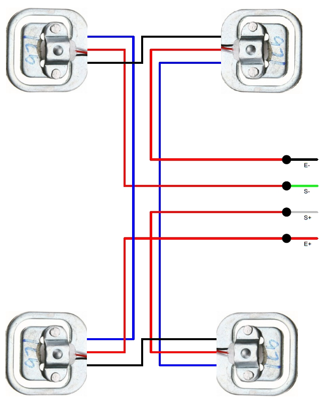
The Bridge Load Sensor typically has four wires for connection. The pinout is as follows:
| Wire Color | Pin Name | Description |
|---|---|---|
| Red | Excitation+ (E+) | Positive voltage input for the Wheatstone bridge |
| Black | Excitation- (E-) | Ground or negative voltage input for the Wheatstone bridge |
| White | Signal+ (S+) | Positive output signal from the Wheatstone bridge |
| Green | Signal- (S-) | Negative output signal from the Wheatstone bridge |
Note: Some models may have different wire colors. Always refer to the datasheet of your specific sensor.
Usage Instructions
How to Use the Component in a Circuit
Connect the Sensor to an Amplifier:
The output signal of the Bridge Load Sensor is in the millivolt range and requires amplification. Use a dedicated amplifier module, such as the HX711, to amplify the signal for further processing.Wiring the Sensor:
- Connect the
E+andE-wires to the positive and negative terminals of the amplifier's excitation input. - Connect the
S+andS-wires to the amplifier's signal input terminals. - Power the amplifier module with a 5V DC supply.
- Connect the
Interface with a Microcontroller:
The amplified signal can be read by a microcontroller (e.g., Arduino UNO) via an analog or digital input pin, depending on the amplifier module used.Calibrate the Sensor:
Perform a calibration process to ensure accurate weight measurements. This involves recording the sensor's output at zero load and at a known reference load.
Important Considerations and Best Practices
- Avoid Overloading: Do not exceed the sensor's maximum load capacity, as this may permanently damage the sensor.
- Stable Mounting: Ensure the sensor is securely mounted to avoid measurement errors caused by vibrations or movement.
- Temperature Effects: Be aware of temperature variations, as they can affect the sensor's accuracy. Use temperature compensation if necessary.
- Shielded Cables: Use shielded cables to minimize noise interference in the signal.
Example Code for Arduino UNO
Below is an example of how to interface a Bridge Load Sensor with an Arduino UNO using the HX711 amplifier module:
#include "HX711.h"

// Define HX711 pins
#define DT 3  // Data pin connected to Arduino digital pin 3
#define SCK 2 // Clock pin connected to Arduino digital pin 2

HX711 scale;

void setup() {
  Serial.begin(9600); // Initialize serial communication
  scale.begin(DT, SCK); // Initialize HX711 with defined pins

  Serial.println("Calibrating... Place a known weight on the sensor.");
  delay(5000); // Wait for user to place a weight
  scale.set_scale(); // Set the scale factor (calibration required)
  scale.tare(); // Reset the scale to zero
  Serial.println("Calibration complete.");
}

void loop() {
  // Read weight from the sensor
  float weight = scale.get_units(10); // Average of 10 readings
  Serial.print("Weight: ");
  Serial.print(weight);
  Serial.println(" kg");

  delay(1000); // Wait 1 second before the next reading
}
Note: Replace
scale.set_scale()with the appropriate calibration factor for your sensor. This value is determined during the calibration process.
Troubleshooting and FAQs
Common Issues and Solutions
No Output Signal:
- Cause: Incorrect wiring or loose connections.
- Solution: Double-check all connections and ensure the wires are securely connected to the amplifier module.
Inconsistent Readings:
- Cause: Vibrations, unstable mounting, or electrical noise.
- Solution: Mount the sensor securely and use shielded cables to reduce noise interference.
Output Signal Saturation:
- Cause: Exceeding the sensor's maximum load capacity.
- Solution: Ensure the applied load is within the sensor's rated capacity.
Incorrect Weight Measurements:
- Cause: Improper calibration.
- Solution: Recalibrate the sensor using a known reference weight.
FAQs
Q: Can I use the Bridge Load Sensor without an amplifier?
A: No, the sensor's output signal is too weak to be directly read by a microcontroller. An amplifier like the HX711 is required.Q: How do I determine the calibration factor?
A: Use a known reference weight and adjust the calibration factor in your code until the sensor outputs the correct weight.Q: Can I use multiple load sensors in a single system?
A: Yes, you can connect multiple sensors in parallel or use a summing junction box, depending on your application.Q: What is the lifespan of a Bridge Load Sensor?
A: With proper usage and within rated specifications, the sensor can last for many years.
This documentation provides a comprehensive guide to understanding, using, and troubleshooting the Bridge Load Sensor. For further details, refer to the datasheet of your specific sensor model.