How to Use Brushless Motor Driver Board: Examples, Pinouts, and Specs
Introduction
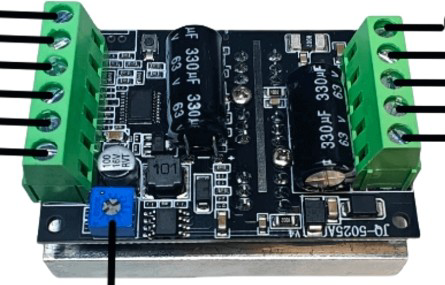
The BLDC BL50V300W Brushless Motor Driver Board is a high-performance circuit board designed to control brushless DC (BLDC) motors. It provides the necessary power and control signals to drive the motor efficiently, ensuring smooth operation and precise speed control. This driver board is equipped with features such as Pulse Width Modulation (PWM) control, overcurrent protection, and thermal protection, making it suitable for a wide range of applications.
Explore Projects Built with Brushless Motor Driver Board
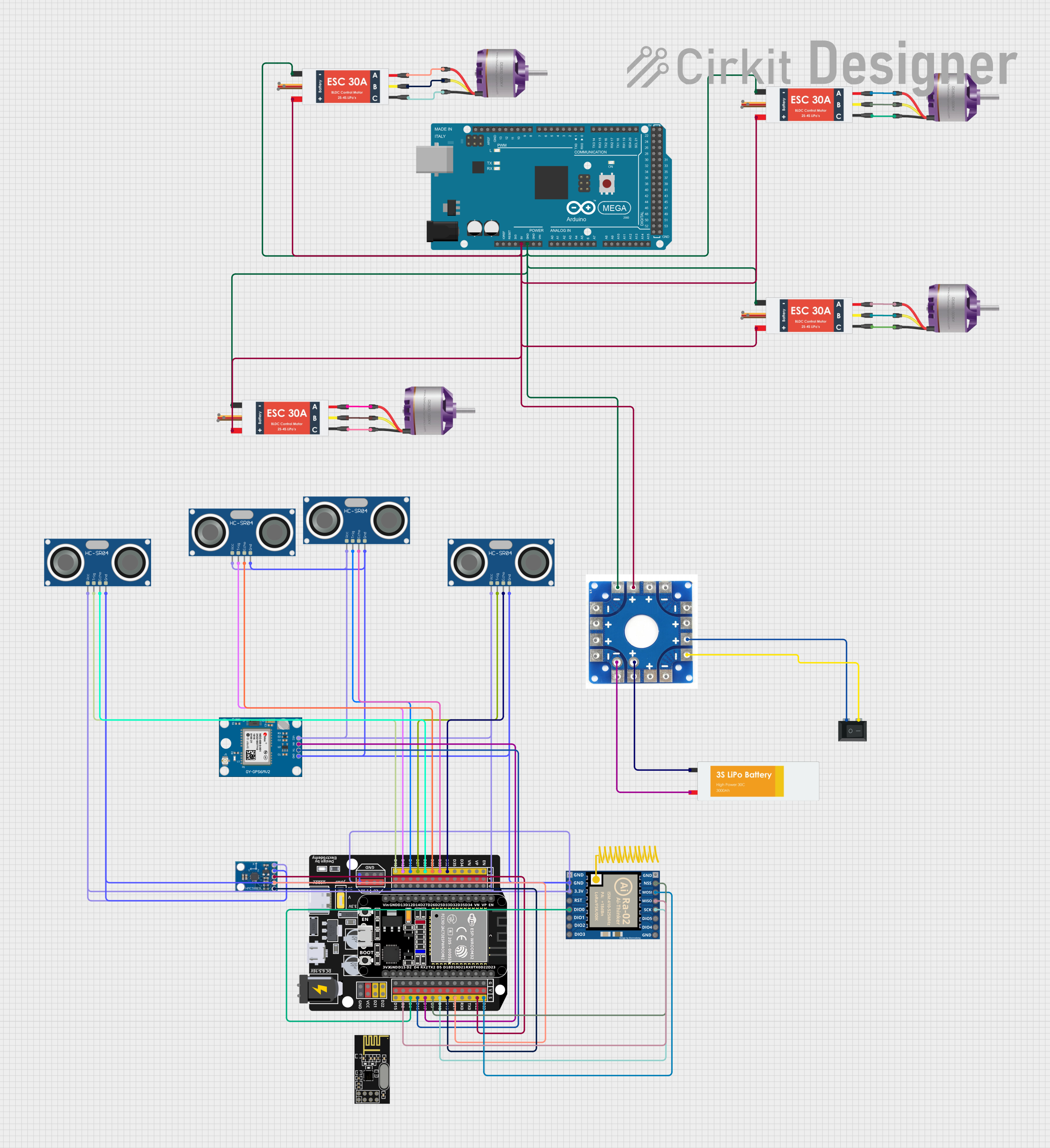

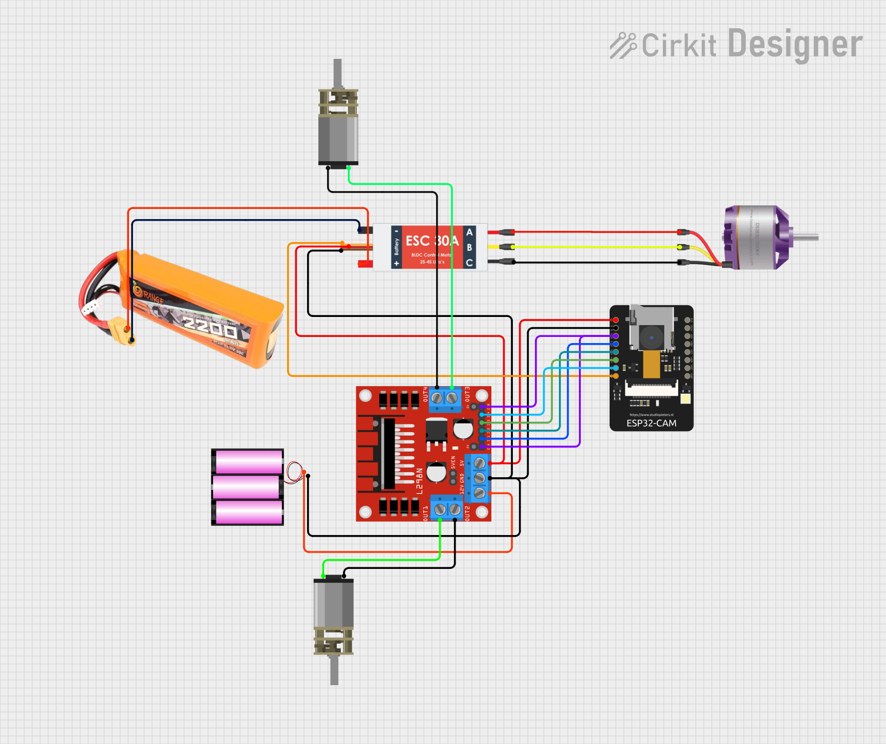
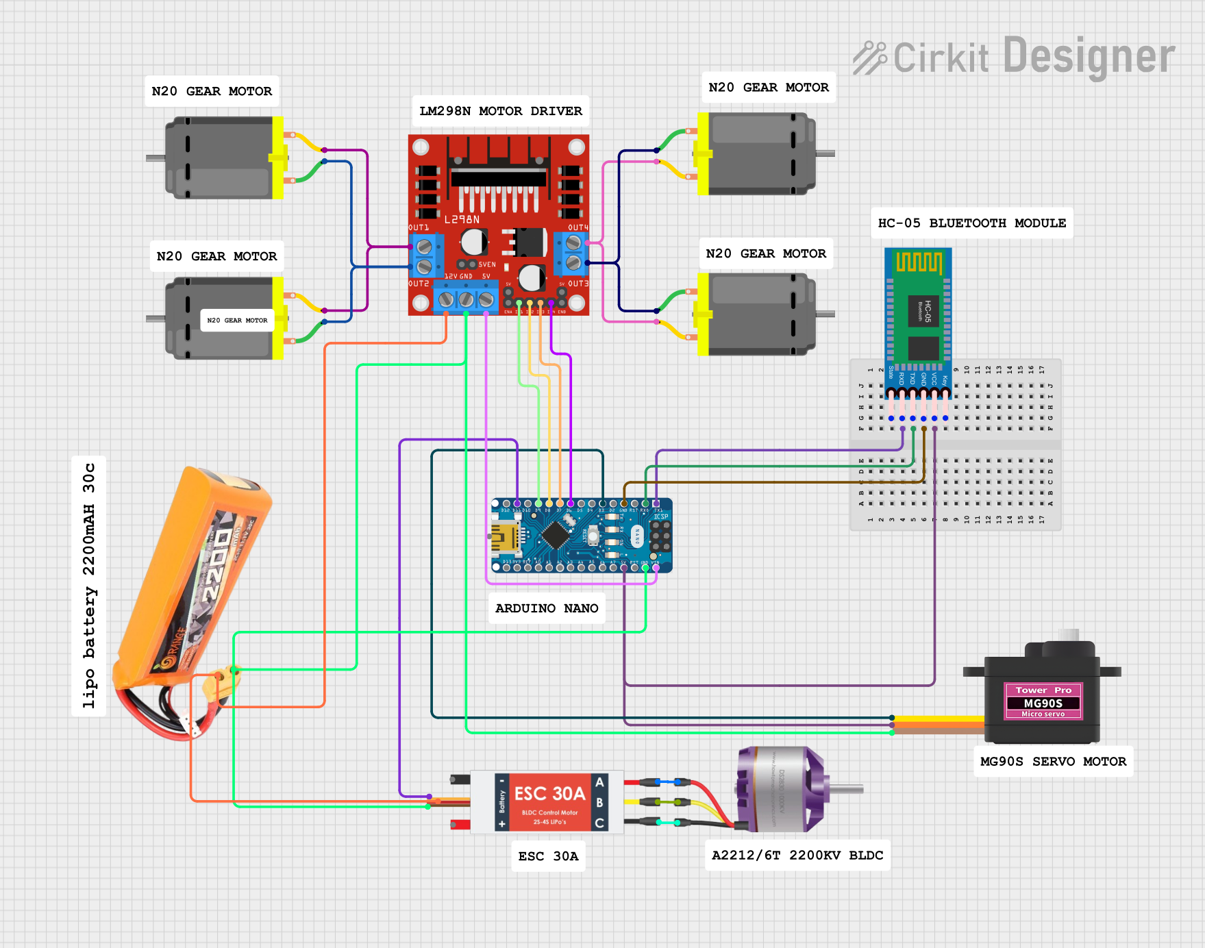
Explore Projects Built with Brushless Motor Driver Board
Common Applications
- Electric vehicles (e-bikes, scooters, drones)
- Industrial automation systems
- Robotics and mechatronics
- HVAC systems (fans, blowers)
- Home appliances (washing machines, air conditioners)
Technical Specifications
Below are the key technical details of the BL50V300W Brushless Motor Driver Board:
| Parameter | Value |
|---|---|
| Manufacturer | BLDC |
| Part ID | BL50V300W |
| Input Voltage Range | 12V - 50V DC |
| Maximum Output Power | 300W |
| Maximum Output Current | 10A |
| Control Signal Type | PWM (Pulse Width Modulation) |
| PWM Frequency Range | 1 kHz - 20 kHz |
| Motor Type Supported | 3-phase brushless DC motors |
| Protection Features | Overcurrent, Overvoltage, Thermal |
| Operating Temperature | -20°C to 85°C |
| Dimensions | 80mm x 60mm x 20mm |
Pin Configuration and Descriptions
The BL50V300W driver board has the following pin configuration:
| Pin Name | Type | Description |
|---|---|---|
| VIN+ | Power Input | Positive terminal for the input voltage (12V - 50V DC). |
| VIN- | Power Input | Negative terminal for the input voltage (ground). |
| U | Motor Output | Phase U connection for the BLDC motor. |
| V | Motor Output | Phase V connection for the BLDC motor. |
| W | Motor Output | Phase W connection for the BLDC motor. |
| PWM | Control Input | PWM signal input for speed control (1 kHz - 20 kHz). |
| GND | Ground | Ground connection for the control signal. |
| EN | Control Input | Enable pin to turn the motor driver on/off (logic HIGH to enable). |
| FG | Feedback Output | Motor speed feedback signal (frequency proportional to motor speed). |
| TEMP | Feedback Output | Temperature monitoring output (analog voltage proportional to board temperature). |
Usage Instructions
How to Use the Component in a Circuit
- Power Supply: Connect a DC power supply (12V - 50V) to the
VIN+andVIN-pins. Ensure the power supply can provide sufficient current for your motor's requirements. - Motor Connection: Connect the three-phase wires of your BLDC motor to the
U,V, andWoutput pins. - Control Signal:
- Connect a PWM signal to the
PWMpin for speed control. The duty cycle of the PWM signal determines the motor speed. - Use the
ENpin to enable or disable the motor driver. Apply a logic HIGH signal to enable the driver.
- Connect a PWM signal to the
- Feedback Signals:
- Use the
FGpin to monitor the motor's speed. The frequency of the signal on this pin is proportional to the motor's RPM. - Use the
TEMPpin to monitor the board's temperature. This can help prevent overheating during operation.
- Use the
- Protection Features: The board includes built-in protection for overcurrent, overvoltage, and thermal conditions. Ensure the operating conditions stay within the specified limits.
Important Considerations and Best Practices
- PWM Signal: Ensure the PWM signal frequency is within the specified range (1 kHz - 20 kHz). A frequency outside this range may cause erratic motor behavior.
- Heat Dissipation: For high-power applications, ensure proper heat dissipation by attaching a heatsink or using active cooling (e.g., a fan).
- Wiring: Use appropriately rated wires for power and motor connections to handle the current without overheating.
- Startup: Gradually increase the PWM duty cycle during startup to avoid sudden surges in current.
- Arduino Integration: The driver board can be easily controlled using an Arduino or similar microcontroller. Below is an example Arduino code snippet for controlling the motor:
// Arduino example for controlling the BL50V300W Brushless Motor Driver Board
const int pwmPin = 9;  // PWM signal pin
const int enPin = 8;   // Enable pin

void setup() {
  pinMode(pwmPin, OUTPUT); // Set PWM pin as output
  pinMode(enPin, OUTPUT);  // Set Enable pin as output

  digitalWrite(enPin, HIGH); // Enable the motor driver
}

void loop() {
  // Gradually increase motor speed
  for (int dutyCycle = 0; dutyCycle <= 255; dutyCycle += 5) {
    analogWrite(pwmPin, dutyCycle); // Set PWM duty cycle (0-255)
    delay(100); // Wait 100ms
  }

  // Gradually decrease motor speed
  for (int dutyCycle = 255; dutyCycle >= 0; dutyCycle -= 5) {
    analogWrite(pwmPin, dutyCycle); // Set PWM duty cycle (0-255)
    delay(100); // Wait 100ms
  }
}
Troubleshooting and FAQs
Common Issues and Solutions
Motor Does Not Spin:
- Ensure the
ENpin is set to logic HIGH. - Verify the power supply voltage is within the specified range (12V - 50V).
- Check the motor connections (
U,V,W) for proper wiring.
- Ensure the
Erratic Motor Behavior:
- Verify the PWM signal frequency is within the 1 kHz - 20 kHz range.
- Check for loose or damaged wires.
Overheating:
- Ensure proper heat dissipation with a heatsink or active cooling.
- Monitor the
TEMPpin output to ensure the board temperature is within safe limits.
No Feedback Signal:
- Check the
FGpin connection and ensure the motor is spinning. - Verify the motor supports feedback signal generation.
- Check the
FAQs
Q: Can I use this driver board with a two-phase motor?
A: No, the BL50V300W is designed specifically for three-phase brushless DC motors.
Q: What happens if the input voltage exceeds 50V?
A: The board's overvoltage protection will activate, and the driver will shut down to prevent damage.
Q: Can I control the motor speed without a microcontroller?
A: Yes, you can use a standalone PWM generator module to provide the control signal.
Q: Is reverse rotation supported?
A: Yes, reverse rotation can be achieved by swapping any two of the motor phase connections (U, V, W).