How to Use SPLIT CHARGE RELAY (VSR): Examples, Pinouts, and Specs
Introduction
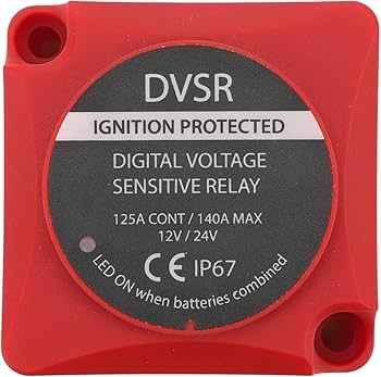
A Split Charge Relay (Voltage Sensitive Relay or VSR) is an automatic relay designed for use in dual battery systems. It ensures efficient charging of a secondary (auxiliary) battery while protecting the primary (starter) battery from being drained. The VSR operates by monitoring the voltage of the primary battery and automatically connecting or disconnecting the secondary battery based on preset voltage thresholds. This makes it an essential component in vehicles with additional power requirements, such as campervans, boats, and off-road vehicles.
Explore Projects Built with SPLIT CHARGE RELAY (VSR)


Explore Projects Built with SPLIT CHARGE RELAY (VSR)
Common Applications and Use Cases
- Dual battery systems in recreational vehicles (RVs) and campervans
- Marine applications for charging auxiliary batteries
- Off-road vehicles with winches or additional lighting
- Solar power systems with multiple batteries
- Emergency vehicles with high power demands
Technical Specifications
Below are the key technical details of a typical Split Charge Relay (VSR):
| Parameter | Value |
|---|---|
| Operating Voltage Range | 12V or 24V systems |
| Cut-In Voltage (Connect) | 13.3V (12V system) / 26.6V (24V system) |
| Cut-Out Voltage (Disconnect) | 12.8V (12V system) / 25.6V (24V system) |
| Maximum Current Rating | 100A to 140A (varies by model) |
| Standby Current Draw | < 5mA |
| Dimensions | Typically 70mm x 70mm x 50mm |
| Operating Temperature Range | -20°C to +60°C |
| Housing Material | ABS plastic or metal |
Pin Configuration and Descriptions
The Split Charge Relay typically has the following terminals:
| Pin/Terminal | Label | Description |
|---|---|---|
| 1 | BATT IN | Connects to the positive terminal of the primary (starter) battery |
| 2 | BATT OUT | Connects to the positive terminal of the secondary (auxiliary) battery |
| 3 | GND | Ground connection for the relay |
| 4 | IGN (Optional) | Optional ignition signal input to manually override or control the relay |
Usage Instructions
How to Use the Split Charge Relay in a Circuit
Wiring the Relay:
- Connect the
BATT INterminal to the positive terminal of the primary (starter) battery using an appropriately rated cable. - Connect the
BATT OUTterminal to the positive terminal of the secondary (auxiliary) battery. - Connect the
GNDterminal to the vehicle chassis or a common ground point. - If the relay has an
IGNterminal, connect it to the ignition switch or a manual control switch (optional).
- Connect the
Fuse Protection:
- Install a fuse or circuit breaker on both the
BATT INandBATT OUTlines to protect the wiring and components. The fuse rating should match the maximum current rating of the relay.
- Install a fuse or circuit breaker on both the
Mounting:
- Securely mount the relay in a location that is protected from excessive heat, moisture, and vibration.
Operation:
- When the primary battery voltage exceeds the cut-in threshold (e.g., 13.3V for a 12V system), the relay will automatically connect the secondary battery for charging.
- When the primary battery voltage drops below the cut-out threshold (e.g., 12.8V for a 12V system), the relay will disconnect the secondary battery to prevent draining the primary battery.
Important Considerations and Best Practices
- Ensure that the relay's current rating matches or exceeds the maximum current draw of your system.
- Use appropriately sized cables to minimize voltage drop and prevent overheating.
- Regularly inspect the connections and wiring for signs of wear or corrosion.
- Avoid mounting the relay near heat sources such as the engine or exhaust system.
Arduino Integration (Optional)
While a Split Charge Relay is typically used in automotive systems, it can also be controlled using an Arduino for custom applications. Below is an example of how to control a VSR with an Arduino:
// Example code to control a Split Charge Relay (VSR) using an Arduino
// This code monitors the primary battery voltage and controls the relay accordingly.

const int relayPin = 7; // Pin connected to the relay's IGN terminal
const int voltagePin = A0; // Analog pin to read battery voltage
const float cutInVoltage = 13.3; // Cut-in voltage threshold (in volts)
const float cutOutVoltage = 12.8; // Cut-out voltage threshold (in volts)

void setup() {
  pinMode(relayPin, OUTPUT); // Set relay pin as output
  digitalWrite(relayPin, LOW); // Ensure relay is off initially
  Serial.begin(9600); // Initialize serial communication for debugging
}

void loop() {
  int sensorValue = analogRead(voltagePin); // Read the voltage sensor
  float batteryVoltage = (sensorValue / 1023.0) * 5.0 * (12.0 / 5.0);
  // Convert analog reading to voltage (adjust scaling as needed)

  Serial.print("Battery Voltage: ");
  Serial.println(batteryVoltage);

  if (batteryVoltage >= cutInVoltage) {
    digitalWrite(relayPin, HIGH); // Turn on the relay
  } else if (batteryVoltage <= cutOutVoltage) {
    digitalWrite(relayPin, LOW); // Turn off the relay
  }

  delay(1000); // Wait for 1 second before the next reading
}
Troubleshooting and FAQs
Common Issues and Solutions
Relay Does Not Engage:
- Cause: Primary battery voltage is below the cut-in threshold.
- Solution: Check the primary battery voltage and ensure it is being charged properly.
Relay Stays Engaged:
- Cause: Voltage sensing circuit is malfunctioning or voltage is not dropping below the cut-out threshold.
- Solution: Verify the voltage levels and inspect the relay for damage.
Excessive Heat from the Relay:
- Cause: Overcurrent or poor ventilation.
- Solution: Ensure the relay's current rating matches the system requirements and improve airflow around the relay.
Secondary Battery Not Charging:
- Cause: Faulty wiring or blown fuse.
- Solution: Inspect all connections and replace any damaged fuses.
FAQs
Q: Can I use a Split Charge Relay with a lithium battery?
A: Yes, but ensure the relay's voltage thresholds are compatible with the lithium battery's charging profile.
Q: Do I need a manual override switch for the relay?
A: A manual override is optional but can be useful for testing or emergency situations.
Q: Can I install the relay in an engine bay?
A: Yes, but ensure it is mounted in a location protected from excessive heat, moisture, and vibration.