How to Use SIM7020e: Examples, Pinouts, and Specs
Introduction
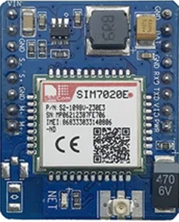
The SIM7020e, manufactured by Esp, is a low-power cellular module designed specifically for IoT (Internet of Things) applications. It supports LTE-M and NB-IoT connectivity, making it ideal for low-bandwidth, energy-efficient communication. With its compact design, built-in GPS functionality, and versatile interfaces, the SIM7020e is well-suited for applications such as smart metering, asset tracking, industrial monitoring, and smart city solutions.
Explore Projects Built with SIM7020e


Explore Projects Built with SIM7020e
Common Applications
- Smart metering (electricity, water, gas)
- Asset and vehicle tracking
- Industrial IoT (IIoT) monitoring
- Smart agriculture and environmental monitoring
- Smart city infrastructure (e.g., parking systems, lighting control)
Technical Specifications
Key Technical Details
| Parameter | Specification |
|---|---|
| Manufacturer | Esp |
| Part ID | SIM7020e |
| Network Support | LTE-M, NB-IoT |
| Frequency Bands | B1/B2/B3/B4/B5/B8/B12/B13/B18/B19/B20/B26/B28 |
| GPS Support | Yes |
| Operating Voltage | 3.1V to 4.2V |
| Power Consumption | 3.5 µA (Power Saving Mode) |
| Data Rate | Uplink: 375 kbps, Downlink: 375 kbps |
| Operating Temperature | -40°C to +85°C |
| Dimensions | 17.6 mm × 15.7 mm × 2.3 mm |
Pin Configuration and Descriptions
The SIM7020e module has multiple pins for power, communication, and control. Below is the pin configuration:
| Pin Number | Pin Name | Description |
|---|---|---|
| 1 | VCC | Power supply input (3.1V to 4.2V) |
| 2 | GND | Ground |
| 3 | TXD | UART Transmit Data |
| 4 | RXD | UART Receive Data |
| 5 | RESET | Reset pin (active low) |
| 6 | PWRKEY | Power-on key (active low) |
| 7 | NETLIGHT | Network status indicator |
| 8 | ANT | Antenna interface |
| 9 | GPIO1 | General-purpose input/output |
| 10 | GPIO2 | General-purpose input/output |
Usage Instructions
How to Use the SIM7020e in a Circuit
- Power Supply: Connect the VCC pin to a stable 3.3V power source and GND to ground. Ensure the power supply can handle peak current demands.
- UART Communication: Connect the TXD and RXD pins to a microcontroller or development board (e.g., Arduino UNO) for serial communication.
- Power On: Use the PWRKEY pin to turn on the module. Pull the pin low for at least 1 second to power up the module.
- Antenna Connection: Attach an appropriate antenna to the ANT pin for reliable network connectivity.
- Network Status: Use the NETLIGHT pin to monitor the network status (e.g., blinking indicates searching for a network).
Important Considerations
- Power Supply: Use a low-noise, stable power source to avoid communication issues.
- Antenna Placement: Place the antenna away from noise sources and ensure it is compatible with the supported frequency bands.
- Firmware Updates: Regularly check for firmware updates from the manufacturer to ensure optimal performance and compatibility.
Example: Connecting SIM7020e to Arduino UNO
Below is an example of how to interface the SIM7020e with an Arduino UNO for basic communication:
Circuit Connections
| SIM7020e Pin | Arduino UNO Pin |
|---|---|
| VCC | 3.3V |
| GND | GND |
| TXD | Pin 10 (RX) |
| RXD | Pin 11 (TX) |
| PWRKEY | Digital Pin 7 |
Arduino Code Example
#include <SoftwareSerial.h>

// Define RX and TX pins for SoftwareSerial
SoftwareSerial SIM7020e(10, 11); // RX = Pin 10, TX = Pin 11

#define PWRKEY 7 // Power key pin

void setup() {
  pinMode(PWRKEY, OUTPUT);
  digitalWrite(PWRKEY, HIGH); // Ensure PWRKEY is high initially

  // Initialize serial communication
  Serial.begin(9600); // Communication with PC
  SIM7020e.begin(9600); // Communication with SIM7020e module

  // Power on the SIM7020e module
  digitalWrite(PWRKEY, LOW); // Pull PWRKEY low
  delay(1000); // Wait for 1 second
  digitalWrite(PWRKEY, HIGH); // Release PWRKEY
  delay(5000); // Wait for the module to initialize

  Serial.println("SIM7020e Initialized");
}

void loop() {
  // Send AT command to check module status
  SIM7020e.println("AT");
  delay(1000);

  // Read response from SIM7020e
  while (SIM7020e.available()) {
    String response = SIM7020e.readString();
    Serial.println(response); // Print response to Serial Monitor
  }
}
Notes:
- Ensure the Arduino UNO is powered via USB or an external power source.
- Use a level shifter if the Arduino operates at 5V logic levels to avoid damaging the SIM7020e.
Troubleshooting and FAQs
Common Issues and Solutions
Module Not Powering On
- Ensure the PWRKEY pin is pulled low for at least 1 second during startup.
- Verify the power supply voltage is within the 3.1V to 4.2V range.
No Network Connection
- Check the antenna connection and placement.
- Verify that the SIM card is inserted correctly and supports LTE-M or NB-IoT.
No Response to AT Commands
- Confirm the UART connections (TXD and RXD) are correct.
- Ensure the baud rate matches the module's default (9600 bps).
High Power Consumption
- Enable Power Saving Mode (PSM) using the appropriate AT command (
AT+CSCLK=1).
- Enable Power Saving Mode (PSM) using the appropriate AT command (
FAQs
Q: Can the SIM7020e be used with 5V microcontrollers?
A: Yes, but a level shifter is required to convert 5V logic levels to 3.3V.Q: How do I update the firmware?
A: Firmware updates can be performed using the manufacturer's tools and instructions. Refer to Esp's official documentation for details.Q: What is the maximum data rate supported?
A: The SIM7020e supports a maximum uplink and downlink data rate of 375 kbps.
By following this documentation, users can effectively integrate the SIM7020e into their IoT projects and troubleshoot common issues.