How to Use RTC: Examples, Pinouts, and Specs
Introduction
A Real-Time Clock (RTC) is a timekeeping device designed to maintain accurate time and date information. It operates independently of the main system clock and continues to function even when the primary power source is disconnected, thanks to an onboard backup battery. RTCs are widely used in applications where precise timekeeping is essential, such as data logging, alarms, scheduling, and real-time event tracking.
Explore Projects Built with RTC
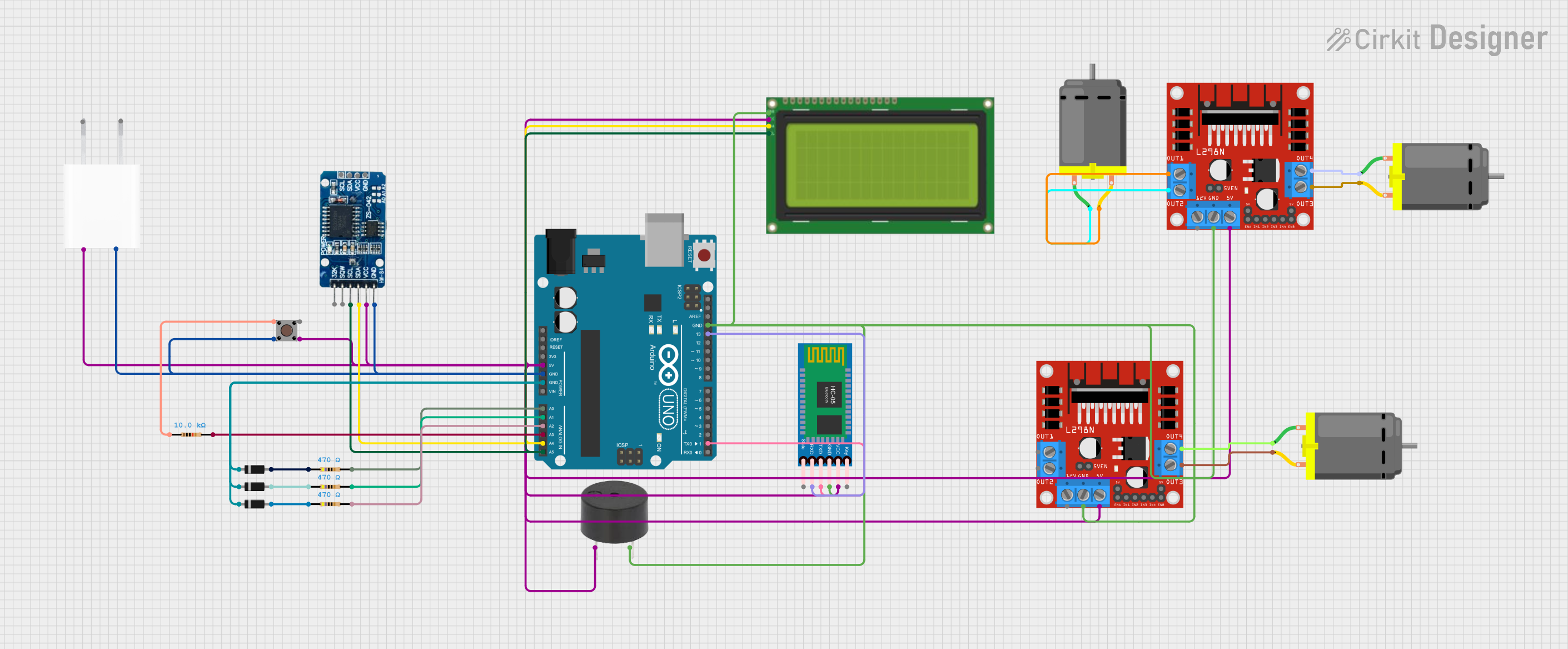
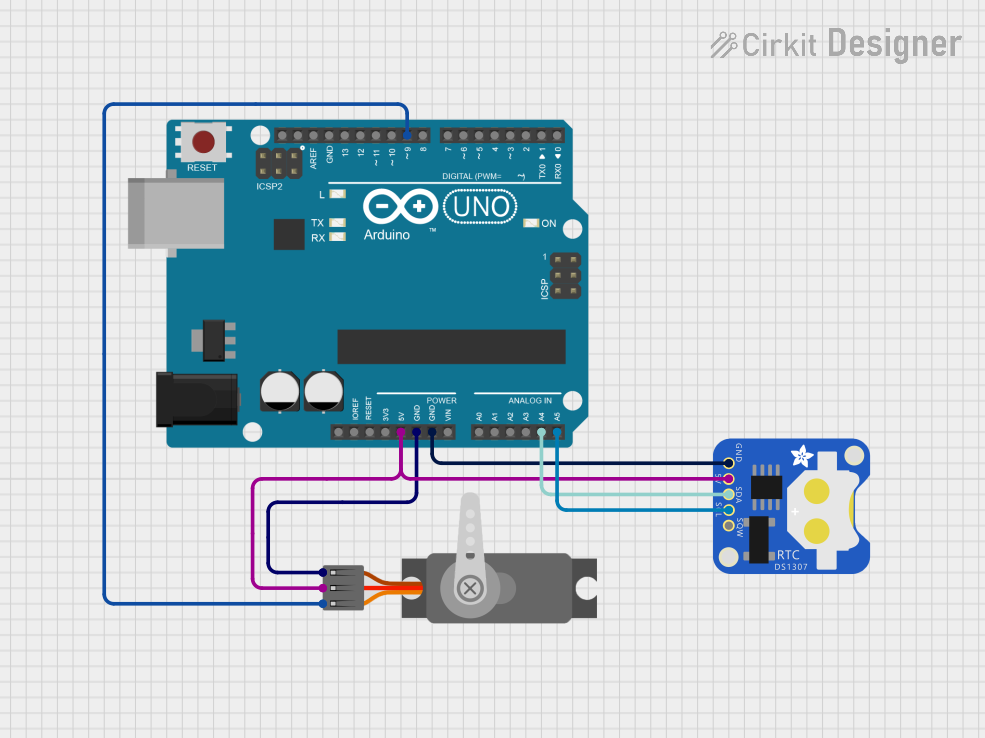

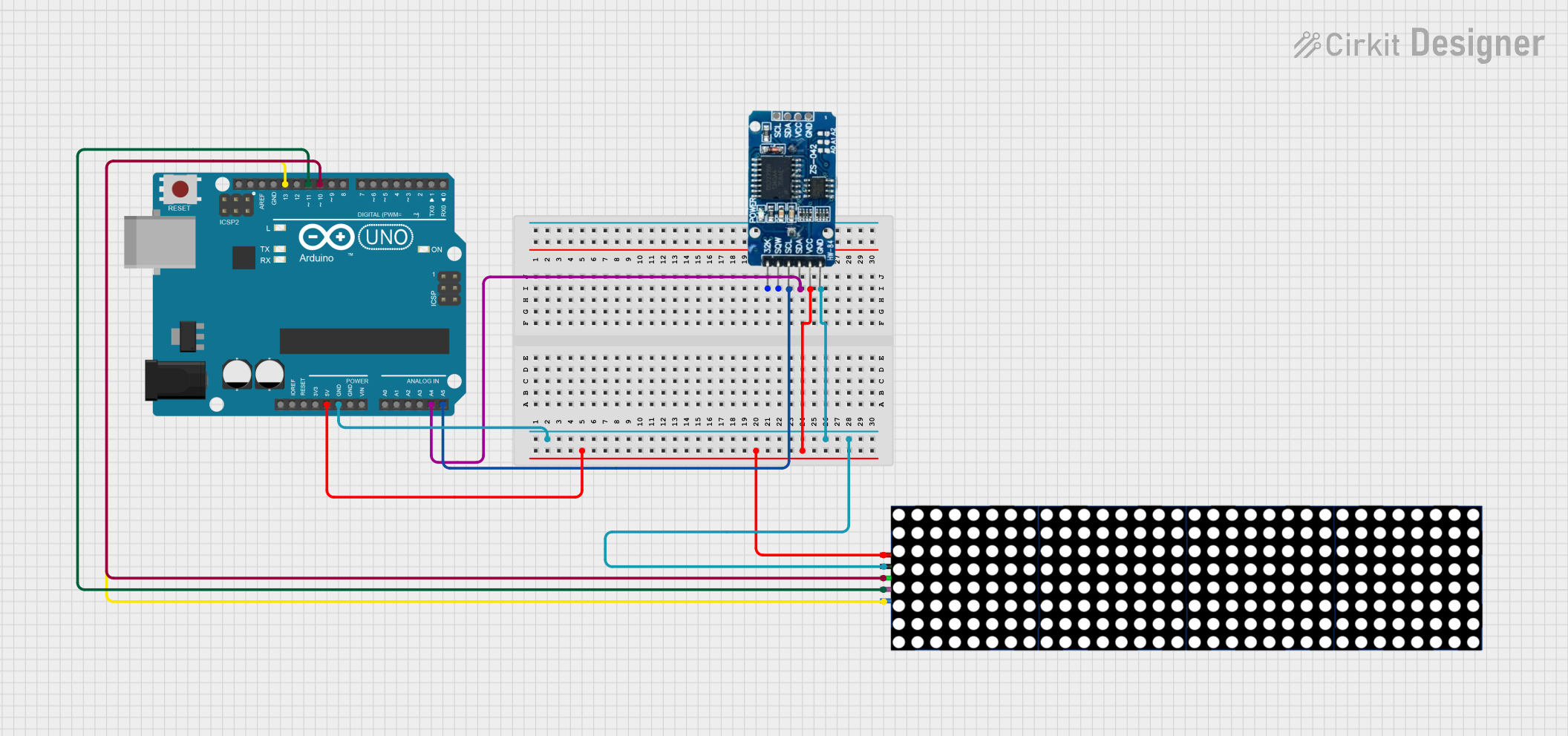
Explore Projects Built with RTC
Common Applications and Use Cases
- Time-stamping data in IoT devices and data loggers
- Maintaining system time in embedded systems
- Alarm clocks and timers
- Scheduling tasks in automation systems
- Time synchronization in communication systems
Technical Specifications
Below are the general technical specifications for a typical RTC module, such as the DS3231 or DS1307:
| Parameter | Specification |
|---|---|
| Operating Voltage | 2.3V to 5.5V |
| Backup Battery Voltage | 3.0V (commonly CR2032 coin cell) |
| Timekeeping Accuracy | ±2 ppm (DS3231) or ±20 ppm (DS1307) |
| Communication Protocol | I2C (Inter-Integrated Circuit) |
| Operating Temperature | -40°C to +85°C |
| Time Format | 24-hour or 12-hour with AM/PM |
| Calendar Support | Tracks seconds, minutes, hours, day, date, month, and year |
| Leap Year Compensation | Automatically adjusts for leap years |
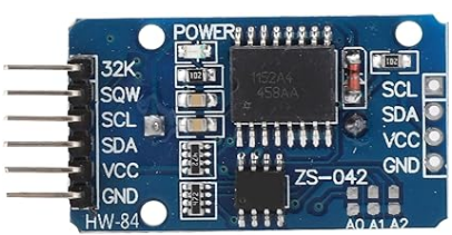
Pin Configuration and Descriptions
The pinout for a typical RTC module (e.g., DS3231 or DS1307) is as follows:
| Pin | Name | Description |
|---|---|---|
| 1 | VCC | Power supply input (2.3V to 5.5V) |
| 2 | GND | Ground connection |
| 3 | SDA | Serial Data Line for I2C communication |
| 4 | SCL | Serial Clock Line for I2C communication |
| 5 | SQW/OUT | Square Wave Output (optional, programmable frequency) |
| 6 | BAT | Backup battery input (commonly connected to a 3V coin cell) |
Usage Instructions
How to Use the RTC in a Circuit
- Power the RTC Module: Connect the VCC pin to a 3.3V or 5V power source and the GND pin to ground.
- Connect I2C Lines: Connect the SDA and SCL pins to the corresponding I2C pins on your microcontroller (e.g., Arduino UNO: SDA = A4, SCL = A5).
- Backup Battery: Insert a 3V coin cell battery into the RTC module's battery holder to ensure timekeeping during power loss.
- Pull-Up Resistors: Ensure that the I2C lines (SDA and SCL) have pull-up resistors (typically 4.7kΩ) if not already included on the module.
Important Considerations and Best Practices
- Battery Life: Use a high-quality coin cell battery to maximize backup time.
- I2C Address: Most RTC modules have a default I2C address (e.g., 0x68 for DS3231/DS1307). Ensure no address conflicts with other I2C devices.
- Time Initialization: The RTC must be initialized with the correct time and date when used for the first time.
- Temperature Compensation: Some RTCs (e.g., DS3231) include temperature compensation for improved accuracy.
Example Code for Arduino UNO
Below is an example of how to interface an RTC module (e.g., DS3231) with an Arduino UNO using the RTClib library:
#include <Wire.h>
#include <RTClib.h>

// Create an RTC object
RTC_DS3231 rtc;

void setup() {
  Serial.begin(9600); // Initialize serial communication
  Wire.begin();       // Initialize I2C communication

  if (!rtc.begin()) {
    Serial.println("RTC not found! Check connections.");
    while (1); // Halt execution if RTC is not detected
  }

  if (rtc.lostPower()) {
    Serial.println("RTC lost power, setting time...");
    // Set the RTC to the current date and time
    rtc.adjust(DateTime(F(__DATE__), F(__TIME__)));
  }
}

void loop() {
  DateTime now = rtc.now(); // Get the current time and date

  // Print the current time and date to the Serial Monitor
  Serial.print(now.year(), DEC);
  Serial.print('/');
  Serial.print(now.month(), DEC);
  Serial.print('/');
  Serial.print(now.day(), DEC);
  Serial.print(" ");
  Serial.print(now.hour(), DEC);
  Serial.print(':');
  Serial.print(now.minute(), DEC);
  Serial.print(':');
  Serial.print(now.second(), DEC);
  Serial.println();

  delay(1000); // Wait for 1 second before updating
}
Troubleshooting and FAQs
Common Issues and Solutions
RTC Not Detected
- Cause: Incorrect wiring or I2C address mismatch.
- Solution: Verify the connections (SDA, SCL, VCC, GND) and ensure the correct I2C address is used in the code.
Incorrect Time or Date
- Cause: RTC not initialized or backup battery depleted.
- Solution: Use the
rtc.adjust()function to set the correct time and replace the backup battery if necessary.
No Output on Serial Monitor
- Cause: Serial communication not initialized or incorrect baud rate.
- Solution: Ensure
Serial.begin(9600)is called insetup()and the Serial Monitor is set to 9600 baud.
RTC Loses Time After Power Loss
- Cause: Backup battery not installed or depleted.
- Solution: Install a new 3V coin cell battery in the RTC module.
FAQs
Q: Can I use the RTC module with a 3.3V microcontroller?
A: Yes, most RTC modules are compatible with both 3.3V and 5V systems. Check the module's datasheet to confirm.
Q: How accurate is the RTC module?
A: Accuracy depends on the specific RTC chip. For example, the DS3231 has an accuracy of ±2 ppm, while the DS1307 has ±20 ppm.
Q: Can I use multiple RTC modules on the same I2C bus?
A: Yes, but each module must have a unique I2C address. Most RTC modules have a fixed address, so additional modules may require address modification.
Q: How long does the backup battery last?
A: A typical CR2032 coin cell battery can last several years, depending on the RTC's power consumption and usage conditions.