How to Use Dual Channel Bidirectional ESC: Examples, Pinouts, and Specs
Introduction
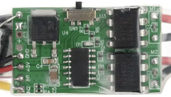
The Dual Channel Bidirectional Electronic Speed Controller (ESC), part ID Dual Brushed ESC, is a versatile motor controller designed for use in remote-controlled (RC) vehicles and robotics. This ESC enables precise control of two brushed DC motors, allowing for bidirectional operation (forward and reverse) and variable speed control. Its dual-channel design makes it ideal for applications requiring independent control of two motors, such as RC cars, boats, and robotic platforms.
Explore Projects Built with Dual Channel Bidirectional ESC


Explore Projects Built with Dual Channel Bidirectional ESC
Common Applications and Use Cases
- RC cars, boats, and other vehicles requiring bidirectional motor control
- Robotics projects, including differential drive systems
- Conveyor belts and automated systems
- DIY projects involving brushed DC motors
Technical Specifications
Key Technical Details
| Parameter | Value |
|---|---|
| Input Voltage Range | 6V to 24V |
| Continuous Current (per channel) | 10A |
| Peak Current (per channel) | 15A (for up to 10 seconds) |
| Motor Type Supported | Brushed DC motors |
| Control Signal Input | PWM (Pulse Width Modulation) |
| PWM Frequency Range | 1 kHz to 20 kHz |
| Direction Control | Bidirectional (forward/reverse) |
| Operating Temperature | -10°C to 60°C |
| Dimensions | 60mm x 40mm x 15mm |
| Weight | 50g |
Pin Configuration and Descriptions
The Dual Channel Bidirectional ESC has the following pin configuration:
Input/Control Pins
| Pin Name | Description |
|---|---|
| VIN | Power input for the ESC (6V to 24V). Connect to the battery or power source. |
| GND | Ground connection. |
| PWM1 | PWM signal input for Channel 1. Controls the speed and direction of Motor 1. |
| PWM2 | PWM signal input for Channel 2. Controls the speed and direction of Motor 2. |
| DIR1 | Direction control input for Channel 1. High = Forward, Low = Reverse. |
| DIR2 | Direction control input for Channel 2. High = Forward, Low = Reverse. |
Output Pins
| Pin Name | Description |
|---|---|
| M1+ | Positive terminal for Motor 1. |
| M1- | Negative terminal for Motor 1. |
| M2+ | Positive terminal for Motor 2. |
| M2- | Negative terminal for Motor 2. |
Usage Instructions
How to Use the Component in a Circuit
- Power Connection: Connect the VIN pin to a DC power source (6V to 24V) and the GND pin to the ground of the power source.
- Motor Connection: Connect the terminals of Motor 1 to M1+ and M1-, and Motor 2 to M2+ and M2-.
- Control Signals:
- Use a microcontroller (e.g., Arduino UNO) to generate PWM signals for PWM1 and PWM2.
- Use digital output pins on the microcontroller to control DIR1 and DIR2 for motor direction.
- Programming: Write a program to send appropriate PWM signals and direction control signals to achieve the desired motor behavior.
Important Considerations and Best Practices
- Ensure the power supply voltage matches the operating range of the ESC and motors.
- Use appropriate heat sinks or cooling mechanisms if operating near the maximum current rating.
- Avoid sudden changes in direction at high speeds to prevent motor or ESC damage.
- Use capacitors across the motor terminals to reduce electrical noise.
Example Code for Arduino UNO
Below is an example Arduino sketch to control two motors using the Dual Channel Bidirectional ESC:
// Pin definitions
const int pwm1 = 3;  // PWM signal for Motor 1
const int dir1 = 4;  // Direction control for Motor 1
const int pwm2 = 5;  // PWM signal for Motor 2
const int dir2 = 6;  // Direction control for Motor 2

void setup() {
  // Set direction pins as outputs
  pinMode(dir1, OUTPUT);
  pinMode(dir2, OUTPUT);

  // Set PWM pins as outputs
  pinMode(pwm1, OUTPUT);
  pinMode(pwm2, OUTPUT);
}

void loop() {
  // Example: Motor 1 forward at 50% speed
  digitalWrite(dir1, HIGH);  // Set direction to forward
  analogWrite(pwm1, 128);    // Set speed (128/255 = 50%)

  // Example: Motor 2 reverse at 75% speed
  digitalWrite(dir2, LOW);   // Set direction to reverse
  analogWrite(pwm2, 192);    // Set speed (192/255 = 75%)

  delay(2000);  // Run for 2 seconds

  // Stop both motors
  analogWrite(pwm1, 0);
  analogWrite(pwm2, 0);

  delay(1000);  // Pause for 1 second
}
Troubleshooting and FAQs
Common Issues and Solutions
Motors Not Running:
- Verify that the power supply voltage is within the specified range.
- Check all connections, especially the motor terminals and control signal pins.
- Ensure the PWM signal is being generated correctly by the microcontroller.
Motor Running in the Wrong Direction:
- Check the DIR1 and DIR2 signal levels. High = Forward, Low = Reverse.
- Swap the motor terminals (M1+ and M1- or M2+ and M2-) if necessary.
Overheating:
- Ensure the ESC is not exceeding its current rating.
- Add a heat sink or cooling fan if operating under high loads.
PWM Signal Not Detected:
- Verify the PWM frequency is within the supported range (1 kHz to 20 kHz).
- Check the microcontroller code for correct PWM pin configuration.
FAQs
Q1: Can this ESC be used with brushless motors?
A1: No, this ESC is designed specifically for brushed DC motors. For brushless motors, use a brushless ESC.
Q2: What happens if I exceed the maximum current rating?
A2: Exceeding the current rating may cause the ESC to overheat or fail. Use motors and loads within the specified limits.
Q3: Can I control both motors independently?
A3: Yes, the dual-channel design allows for independent control of each motor using separate PWM and direction signals.
Q4: Is this ESC compatible with 3.3V logic microcontrollers?
A4: Yes, the control inputs are compatible with both 3.3V and 5V logic levels.
Q5: How do I reverse the motor direction?
A5: Toggle the DIR1 or DIR2 pin (HIGH for forward, LOW for reverse) to change the direction of the respective motor.