Cirkit Designer
Your all-in-one circuit design IDE
Home /
Component Documentation
How to Use 4xAA_JST: Examples, Pinouts, and Specs

Introduction
The 4xAA Battery Holder with JST Connector is a simple and convenient way to power a wide range of electronic projects. This component is designed to hold four AA batteries, providing a portable power source that can be easily connected to various devices through its JST connector. Common applications include powering small motors, Arduino boards, LED strips, and portable electronic devices.
Explore Projects Built with 4xAA_JST
Battery-Powered Multi-Voltage Supply with Barrel Jack Connectors

This circuit consists of multiple 9V batteries connected in series and parallel configurations to provide power to three separate 2.1mm barrel jacks. Each barrel jack receives a different combination of series and parallel battery connections to achieve the desired voltage and current levels.
Battery-Powered ESP32-S3 Controlled Servo System with gForceJoint UART

This circuit is a servo control system powered by a 4 x AAA battery pack, regulated by a step-down DC regulator. An ESP32-S3 microcontroller controls five servos and communicates with a gForceJoint UART sensor, enabling precise servo movements based on sensor inputs.
Arduino Mega 2560 Battery-Powered Dual Servo Joystick Controller
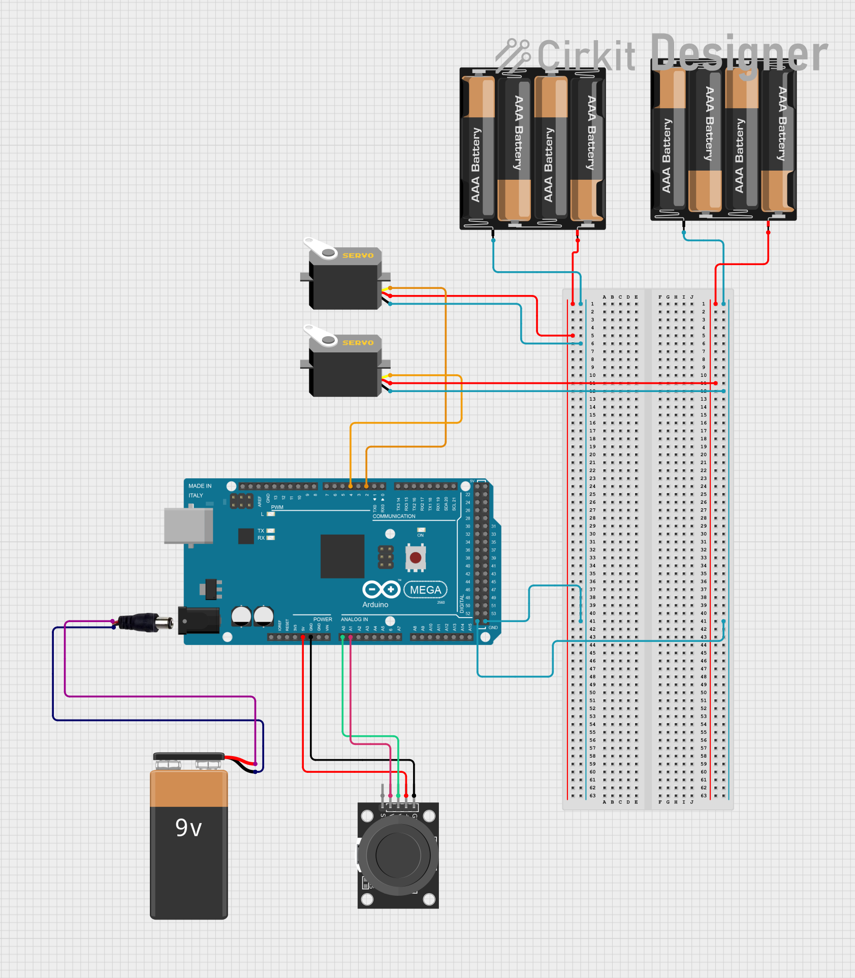
This circuit uses an Arduino Mega 2560 to control two servos based on input from a KY-023 Dual Axis Joystick Module. The servos are powered by separate 4 x AAA battery mounts, while the joystick module is powered by the Arduino. A 9V battery connected to a power jack provides additional power to the Arduino.
Battery-Powered LED Circuit with Pushbutton Control and Capacitance Smoothing
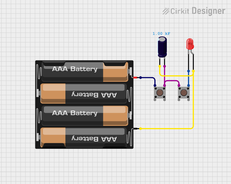
This circuit consists of a 4 x AAA battery mount providing power, two pushbuttons acting as switches, an electrolytic capacitor for smoothing voltage fluctuations, and a red LED as an indicator. The LED lights up when either pushbutton is pressed, with the capacitor likely serving to debounce the pushbutton signal or provide a more stable LED operation. There is no microcontroller in this circuit, indicating a simple, direct-control user interface.
Explore Projects Built with 4xAA_JST
Battery-Powered Multi-Voltage Supply with Barrel Jack Connectors
This circuit consists of multiple 9V batteries connected in series and parallel configurations to provide power to three separate 2.1mm barrel jacks. Each barrel jack receives a different combination of series and parallel battery connections to achieve the desired voltage and current levels.
Battery-Powered ESP32-S3 Controlled Servo System with gForceJoint UART
This circuit is a servo control system powered by a 4 x AAA battery pack, regulated by a step-down DC regulator. An ESP32-S3 microcontroller controls five servos and communicates with a gForceJoint UART sensor, enabling precise servo movements based on sensor inputs.
Arduino Mega 2560 Battery-Powered Dual Servo Joystick Controller
This circuit uses an Arduino Mega 2560 to control two servos based on input from a KY-023 Dual Axis Joystick Module. The servos are powered by separate 4 x AAA battery mounts, while the joystick module is powered by the Arduino. A 9V battery connected to a power jack provides additional power to the Arduino.
Battery-Powered LED Circuit with Pushbutton Control and Capacitance Smoothing
This circuit consists of a 4 x AAA battery mount providing power, two pushbuttons acting as switches, an electrolytic capacitor for smoothing voltage fluctuations, and a red LED as an indicator. The LED lights up when either pushbutton is pressed, with the capacitor likely serving to debounce the pushbutton signal or provide a more stable LED operation. There is no microcontroller in this circuit, indicating a simple, direct-control user interface.
Technical Specifications
General Specifications
- Battery Type: AA
- Number of Batteries: 4
- Nominal Voltage Output: 6V (1.5V per AA battery)
- Maximum Recommended Current: Depends on the batteries used
- Connector Type: JST PH 2.0mm 2-pin
- Cable Length: Typically 150mm
- Material: Plastic casing with metal contacts
- Dimensions: Varies by manufacturer
Pin Configuration and Descriptions
| Pin Number | Description |
|---|---|
| 1 | Positive Voltage (+) |
| 2 | Ground (-) |
Usage Instructions
Installing Batteries
- Open the battery holder's cover by sliding or unclipping it, depending on the design.
- Insert four AA batteries following the polarity markings inside the holder.
- Close the cover securely to ensure good contact between the batteries and the terminals.
Connecting to a Circuit
- Identify the polarity of the JST connector; the red wire is typically positive (+), and the black wire is negative (-).
- Connect the JST connector to the corresponding female JST connector on your device or circuit, ensuring correct polarity.
- If connecting to a breadboard or other component without a JST connector, you may need to use a JST to breadboard adapter or solder the wires directly to the appropriate points in your circuit.
Best Practices
- Always check the polarity before connecting the battery holder to your circuit to prevent damage.
- Use batteries with the same brand and charge level to ensure even discharge and prevent leakage.
- Remove batteries if the device will not be used for an extended period to avoid battery corrosion.
- Do not exceed the recommended current draw for the batteries used, as this can cause overheating or damage.
Troubleshooting and FAQs
Common Issues
- Device not powering on: Ensure batteries are correctly installed, the holder's cover is closed properly, and the JST connector is securely connected.
- Intermittent power: Check for loose connections or damaged wires. Also, inspect the battery contacts for corrosion or dirt.
FAQs
Q: Can I use rechargeable AA batteries with this holder?
- A: Yes, rechargeable AA batteries can be used, but ensure they are all of the same type and charge level.
Q: What is the maximum voltage this holder can provide?
- A: With four alkaline AA batteries, it can provide up to 6V. If using rechargeable NiMH batteries, the voltage might be slightly lower, around 4.8V to 5.6V.
Q: How do I know when to replace the batteries?
- A: Monitor the voltage output or observe the performance of your device. When the device operates slower or with less power, it's time to check and possibly replace the batteries.
Example Arduino UNO Connection
// This example assumes you are using the 4xAA Battery Holder to power an Arduino UNO
// through its external power jack or VIN pin.

void setup() {
  // Initialize digital pin LED_BUILTIN as an output.
  pinMode(LED_BUILTIN, OUTPUT);
}

void loop() {
  // Turn the LED on (HIGH is the voltage level)
  digitalWrite(LED_BUILTIN, HIGH);
  // Wait for a second
  delay(1000);
  // Turn the LED off by making the voltage LOW
  digitalWrite(LED_BUILTIN, LOW);
   // Wait for a second
  delay(1000);
}

// Note: Always ensure that the voltage supplied to the Arduino UNO does not exceed
// the recommended limits. For the UNO, the recommended input voltage range is 7-12V.
// Directly connecting the 6V from the battery holder to the VIN pin is acceptable,
// but the voltage regulator on the Arduino will have less overhead, and the 5V rail
// may be slightly under 5V, especially as the batteries begin to drain.
Remember to always check the Arduino UNO's specifications for the acceptable voltage range and ensure that the power supplied by the battery holder is within this range.