
How to Use Pi UPS Hat : Examples, Pinouts, and Specs
 Design with Pi UPS Hat in Cirkit Designer
Introduction
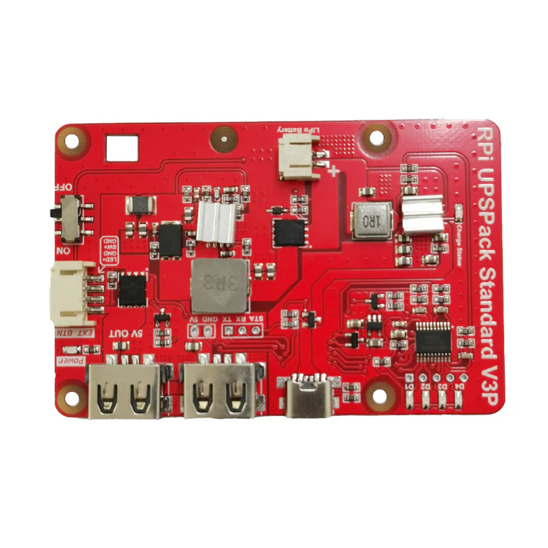
The Pi UPS Hat by MakerFocus is an uninterruptible power supply (UPS) add-on designed specifically for Raspberry Pi boards. This compact and efficient module ensures that your Raspberry Pi remains powered during unexpected power outages, preventing data loss and enabling safe shutdowns. It is particularly useful for applications requiring high reliability, such as IoT devices, servers, and remote monitoring systems.
Explore Projects Built with Pi UPS Hat
 Open Project in Cirkit Designer
 Open Project in Cirkit Designer
 Open Project in Cirkit Designer
 Open Project in Cirkit Designer
Explore Projects Built with Pi UPS Hat
Open Project in Cirkit DesignerOpen Project in Cirkit DesignerOpen Project in Cirkit DesignerOpen Project in Cirkit DesignerCommon Applications and Use Cases
- IoT Projects: Ensures uninterrupted operation of Raspberry Pi-based IoT devices.
- Home Automation: Prevents disruptions in smart home systems during power failures.
- Data Logging: Protects data integrity in logging applications by providing backup power.
- Remote Monitoring: Keeps remote systems operational during outages.
- Educational Projects: Demonstrates power management concepts in Raspberry Pi projects.
Technical Specifications
The Pi UPS Hat is designed to integrate seamlessly with Raspberry Pi boards, offering robust power management features. Below are the key technical details:
General Specifications
| Parameter | Value |
|---|---|
| Input Voltage | 5V DC (via micro-USB or GPIO pins) |
| Output Voltage | 5V DC |
| Maximum Output Current | 2.5A |
| Battery Type | Lithium-ion or Lithium-polymer |
| Battery Capacity Range | 1000mAh to 5000mAh (recommended) |
| Charging Current | 1A (max) |
| Dimensions | 65mm x 56mm x 20mm |
| Weight | ~30g (excluding battery) |
Pin Configuration and Descriptions
The Pi UPS Hat connects to the Raspberry Pi via the GPIO header. Below is the pin configuration:
| Pin Number | Pin Name | Description |
|---|---|---|
| 2 (5V) | 5V Power Input | Supplies power to the Raspberry Pi. |
| 6 (GND) | Ground | Common ground connection. |
| 7 (GPIO4) | Power Status | Indicates the power status (high = normal). |
| 11 (GPIO17) | Battery Status | Indicates battery level (low = low battery). |
| 13 (GPIO27) | Shutdown Signal | Used to trigger safe shutdown of the Raspberry Pi. |
Usage Instructions
How to Use the Pi UPS Hat in a Circuit
- Attach the Hat: Align the Pi UPS Hat with the GPIO header of your Raspberry Pi and gently press it into place.
- Connect a Battery: Attach a compatible lithium-ion or lithium-polymer battery to the battery connector on the Hat.
- Power the Hat: Supply 5V DC power to the Hat via the micro-USB port or GPIO pins.
- Monitor Status: Use the GPIO pins to monitor power and battery status. Optionally, configure scripts to handle safe shutdowns.
Important Considerations and Best Practices
- Battery Selection: Use a battery with a capacity between 1000mAh and 5000mAh for optimal performance.
- Safe Shutdown: Configure a script to monitor the battery status and initiate a safe shutdown when the battery is low.
- Heat Management: Ensure proper ventilation to prevent overheating, especially under high loads.
- Firmware Updates: Check the manufacturer's website for firmware updates or additional software tools.
Example Code for Raspberry Pi
Below is an example Python script to monitor the power and battery status using GPIO pins:
import RPi.GPIO as GPIO
import time
Pin configuration
POWER_STATUS_PIN = 4 # GPIO4 for power status BATTERY_STATUS_PIN = 17 # GPIO17 for battery status SHUTDOWN_SIGNAL_PIN = 27 # GPIO27 for shutdown signal
GPIO setup
GPIO.setmode(GPIO.BCM) GPIO.setup(POWER_STATUS_PIN, GPIO.IN) GPIO.setup(BATTERY_STATUS_PIN, GPIO.IN) GPIO.setup(SHUTDOWN_SIGNAL_PIN, GPIO.OUT)
try: while True: power_status = GPIO.input(POWER_STATUS_PIN) battery_status = GPIO.input(BATTERY_STATUS_PIN)
    # Check power status
    if power_status == GPIO.HIGH:
        print("Power supply is normal.")
    else:
        print("Power supply is disconnected. Running on battery.")

    # Check battery status
    if battery_status == GPIO.LOW:
        print("Battery is low! Consider shutting down.")
        # Trigger safe shutdown signal
        GPIO.output(SHUTDOWN_SIGNAL_PIN, GPIO.HIGH)
        time.sleep(1)
        GPIO.output(SHUTDOWN_SIGNAL_PIN, GPIO.LOW)

    time.sleep(5)  # Check status every 5 seconds
except KeyboardInterrupt: print("Exiting program.") finally: GPIO.cleanup()
Notes:
- Install the
RPi.GPIOlibrary before running the script:pip install RPi.GPIO. - Modify the GPIO pin numbers in the script if your setup differs.
Troubleshooting and FAQs
Common Issues and Solutions
The Raspberry Pi does not power on when using the Hat.
- Ensure the battery is properly connected and charged.
- Verify that the input power supply provides 5V DC and sufficient current.
The battery does not charge.
- Check the battery connection and ensure it is compatible with the Hat.
- Confirm that the input power supply is connected and functioning.
The Raspberry Pi shuts down unexpectedly.
- Monitor the battery status using the GPIO pins to ensure the battery is not depleted.
- Use a higher-capacity battery if your application requires extended backup time.
The Hat overheats during operation.
- Ensure adequate ventilation around the Raspberry Pi and the Hat.
- Avoid exceeding the maximum output current of 2.5A.
FAQs
Q: Can I use the Pi UPS Hat with other single-board computers?
A: The Hat is designed for Raspberry Pi boards but may work with other SBCs that have a compatible GPIO header and 5V power requirements.
Q: How long can the Hat power my Raspberry Pi during an outage?
A: Backup time depends on the battery capacity and the power consumption of your Raspberry Pi. For example, a 3000mAh battery can provide approximately 2-3 hours of backup for a typical Raspberry Pi 4.
Q: Is it safe to leave the battery connected all the time?
A: Yes, the Hat includes built-in charging and protection circuits to prevent overcharging and over-discharging.
Q: Can I monitor the battery level programmatically?
A: Yes, you can use the GPIO pins to monitor the battery status and trigger actions based on the readings.
This concludes the documentation for the Pi UPS Hat by MakerFocus. For further assistance, refer to the manufacturer's website or community forums.