Cirkit Designer Logo
Cirkit Designer
Your all-in-one circuit design IDE
Home / 
Component Documentation

How to Use TVS-Diode SMBJ28CA: Examples, Pinouts, and Specs

Image of TVS-Diode SMBJ28CA
Cirkit Designer LogoDesign with TVS-Diode SMBJ28CA in Cirkit Designer

Introduction

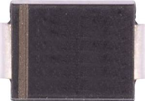
The SMBJ28CA is a bidirectional Transient Voltage Suppressor (TVS) diode manufactured by Diodes Incorporated. It is designed to protect sensitive electronic components from voltage spikes, electrostatic discharge (ESD), and other transient events. With a standoff voltage of 28V and a robust clamping capability, the SMBJ28CA is ideal for safeguarding power supply circuits, data lines, and other critical electronic systems.

Explore Projects Built with TVS-Diode SMBJ28CA

Use Cirkit Designer to design, explore, and prototype these projects online. Some projects support real-time simulation. Click "Open Project" to start designing instantly!
T-Beam with I2C OLED Display Interface
Image of MQTT_Node: A project utilizing TVS-Diode SMBJ28CA in a practical application
This circuit connects a T-Beam microcontroller board with an OLED 128x64 I2C Monochrome Display. The T-Beam's I2C pins (SDA and SCL) are wired to the corresponding SDA and SCK pins on the OLED display, allowing for communication between the microcontroller and the display. Power and ground connections are also established, with the display's VDD connected to the T-Beam's 3V3 output, and GND to GND, to complete the power circuit for the display.
Cirkit Designer LogoOpen Project in Cirkit Designer
Arduino Pro Mini FM Radio with LCD Display and Battery Power
Image of DIY FM Radio RDA5807M V2: A project utilizing TVS-Diode SMBJ28CA in a practical application
This circuit is a portable FM radio receiver with an integrated display and audio output. It uses an Arduino Pro Mini to control an RDA5807M FM receiver module, an ADS1115 ADC for additional analog inputs, and a PAM8403 amplifier to drive loudspeakers. The circuit also includes a rotary encoder for user input, an LCD screen for displaying information, and a boost converter for power management.
Cirkit Designer LogoOpen Project in Cirkit Designer
Arduino-Controlled 4-Channel RF Decoder Data Display with I2C LCD Interface
Image of FYP: A project utilizing TVS-Diode SMBJ28CA in a practical application
This circuit comprises an Arduino UNO microcontroller interfaced with four 2-to-12 series CMOS decoders, a 433 MHz RF receiver module, four 1MΩ resistors, four red LEDs, and a 20x4 I2C LCD display. The Arduino reads 3-bit data from each decoder, which are likely receiving signals from the RF receiver, and displays the binary data on the LCD. The LEDs are connected to the decoders' VT (valid transmission) pins, indicating successful data reception, and the entire circuit is powered by a 5V DC source.
Cirkit Designer LogoOpen Project in Cirkit Designer
Battery-Powered LED Indicator Circuit with BC547 Transistors
Image of traffic light: A project utilizing TVS-Diode SMBJ28CA in a practical application
This circuit is a multi-stage transistor-based LED driver powered by a 9V battery, controlled by a rocker switch. It uses three BC547 transistors to drive three LEDs (red, green, and yellow) with the help of resistors and capacitors to manage current and voltage levels.
Cirkit Designer LogoOpen Project in Cirkit Designer

Explore Projects Built with TVS-Diode SMBJ28CA

Use Cirkit Designer to design, explore, and prototype these projects online. Some projects support real-time simulation. Click "Open Project" to start designing instantly!
Image of MQTT_Node: A project utilizing TVS-Diode SMBJ28CA in a practical application
T-Beam with I2C OLED Display Interface
This circuit connects a T-Beam microcontroller board with an OLED 128x64 I2C Monochrome Display. The T-Beam's I2C pins (SDA and SCL) are wired to the corresponding SDA and SCK pins on the OLED display, allowing for communication between the microcontroller and the display. Power and ground connections are also established, with the display's VDD connected to the T-Beam's 3V3 output, and GND to GND, to complete the power circuit for the display.
Cirkit Designer LogoOpen Project in Cirkit Designer
Image of DIY FM Radio RDA5807M V2: A project utilizing TVS-Diode SMBJ28CA in a practical application
Arduino Pro Mini FM Radio with LCD Display and Battery Power
This circuit is a portable FM radio receiver with an integrated display and audio output. It uses an Arduino Pro Mini to control an RDA5807M FM receiver module, an ADS1115 ADC for additional analog inputs, and a PAM8403 amplifier to drive loudspeakers. The circuit also includes a rotary encoder for user input, an LCD screen for displaying information, and a boost converter for power management.
Cirkit Designer LogoOpen Project in Cirkit Designer
Image of FYP: A project utilizing TVS-Diode SMBJ28CA in a practical application
Arduino-Controlled 4-Channel RF Decoder Data Display with I2C LCD Interface
This circuit comprises an Arduino UNO microcontroller interfaced with four 2-to-12 series CMOS decoders, a 433 MHz RF receiver module, four 1MΩ resistors, four red LEDs, and a 20x4 I2C LCD display. The Arduino reads 3-bit data from each decoder, which are likely receiving signals from the RF receiver, and displays the binary data on the LCD. The LEDs are connected to the decoders' VT (valid transmission) pins, indicating successful data reception, and the entire circuit is powered by a 5V DC source.
Cirkit Designer LogoOpen Project in Cirkit Designer
Image of traffic light: A project utilizing TVS-Diode SMBJ28CA in a practical application
Battery-Powered LED Indicator Circuit with BC547 Transistors
This circuit is a multi-stage transistor-based LED driver powered by a 9V battery, controlled by a rocker switch. It uses three BC547 transistors to drive three LEDs (red, green, and yellow) with the help of resistors and capacitors to manage current and voltage levels.
Cirkit Designer LogoOpen Project in Cirkit Designer

Common Applications

  • Protection of power supply circuits from voltage transients
  • Safeguarding data and signal lines in communication systems
  • ESD protection in industrial and consumer electronics
  • Automotive electronics and control systems

Technical Specifications

Key Specifications

Parameter Value
Manufacturer Diodes Incorporated
Part Number SMBJ28CA
Breakdown Voltage (VBR) 31.1V (min) to 34.4V (max)
Reverse Standoff Voltage (VRWM) 28V
Clamping Voltage (VC) 45.4V (max)
Peak Pulse Current (IPP) 13.2A (max)
Power Dissipation (PPP) 600W (10/1000 µs waveform)
Package Type DO-214AA (SMB)
Polarity Bidirectional
Operating Temperature -55°C to +150°C
Storage Temperature -55°C to +150°C

Pin Configuration

The SMBJ28CA is a two-terminal device with no polarity marking, as it is bidirectional. The pin configuration is as follows:

Pin Number Description
1 Cathode/Anode (Bidirectional)
2 Cathode/Anode (Bidirectional)

Usage Instructions

How to Use the SMBJ28CA in a Circuit

  1. Placement in Circuit:

    • Connect the SMBJ28CA across the component or circuit you want to protect.
    • For power supply protection, place the diode between the power line and ground.
    • For data line protection, connect the diode between the signal line and ground.
  2. Polarity:

    • The SMBJ28CA is bidirectional, so it does not have a specific polarity. This makes it suitable for AC signals or bidirectional data lines.
  3. Voltage Selection:

    • Ensure the reverse standoff voltage (28V) is higher than the normal operating voltage of the circuit.
    • The breakdown voltage (31.1V to 34.4V) should be within the acceptable range for transient suppression.
  4. PCB Layout Considerations:

    • Minimize the trace length between the diode and the protected component to reduce inductance.
    • Use wide traces to handle high transient currents.

Important Considerations

  • Power Dissipation: Ensure the diode can handle the peak power dissipation (600W) during transient events.
  • Thermal Management: If the diode is expected to handle frequent transients, consider thermal management techniques to prevent overheating.
  • ESD Protection: For ESD-sensitive applications, place the diode as close as possible to the input/output connector.

Example: Using SMBJ28CA with an Arduino UNO

To protect an Arduino UNO's 5V power supply from voltage spikes, you can connect the SMBJ28CA as follows:

  1. Connect one terminal of the SMBJ28CA to the 5V line.
  2. Connect the other terminal to the ground (GND) line.

Here is an example Arduino sketch to demonstrate a simple circuit with transient protection:

// Example: Simple LED Blink with TVS Diode Protection
// This sketch demonstrates a basic LED blink circuit.
// The SMBJ28CA is used to protect the Arduino's 5V line from voltage spikes.

const int ledPin = 13; // Pin connected to the onboard LED

void setup() {
  pinMode(ledPin, OUTPUT); // Set the LED pin as an output
}

void loop() {
  digitalWrite(ledPin, HIGH); // Turn the LED on
  delay(1000);                // Wait for 1 second
  digitalWrite(ledPin, LOW);  // Turn the LED off
  delay(1000);                // Wait for 1 second
}

Note: The SMBJ28CA is not directly involved in the code but protects the Arduino's power supply from transients.

Troubleshooting and FAQs

Common Issues and Solutions

Issue Possible Cause Solution
Diode overheating Excessive transient power dissipation Ensure the transient power is within the diode's 600W rating. Use proper thermal management.
Circuit not protected from transients Incorrect placement of the diode Verify the diode is connected across the protected component or circuit.
Voltage clamping not effective Operating voltage exceeds standoff voltage Ensure the circuit's operating voltage is below 28V. Use a TVS diode with a higher standoff voltage if needed.

FAQs

  1. Can the SMBJ28CA be used for AC circuits?
    Yes, the SMBJ28CA is bidirectional and can protect AC circuits or bidirectional signal lines.

  2. What happens if the diode is exposed to continuous overvoltage?
    Continuous overvoltage beyond the standoff voltage may cause the diode to conduct continuously, leading to overheating and potential failure.

  3. How do I select the right TVS diode for my application?
    Consider the following parameters: reverse standoff voltage, breakdown voltage, clamping voltage, peak pulse current, and power dissipation. Ensure these values align with your circuit's requirements.

  4. Can I use the SMBJ28CA for automotive applications?
    Yes, the SMBJ28CA is suitable for automotive applications, provided the voltage and power ratings match the system requirements.

By following this documentation, you can effectively integrate the SMBJ28CA into your designs and protect your circuits from harmful transients.