
How to Use V_REG_LD1085: Examples, Pinouts, and Specs

 Design with V_REG_LD1085 in Cirkit Designer
Introduction
The LD1085 is a low-dropout (LDO) voltage regulator designed to provide a stable and reliable output voltage with a maximum output current of 3A. Its low dropout voltage makes it ideal for applications where the input voltage is close to the desired output voltage. The LD1085 is widely used in power supply circuits for microcontrollers, sensors, and other electronic devices that require precise voltage regulation.
Explore Projects Built with V_REG_LD1085
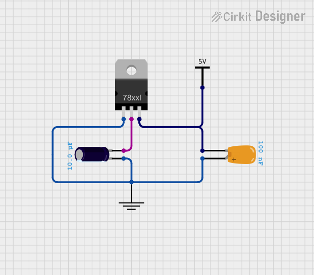 Open Project in Cirkit Designer
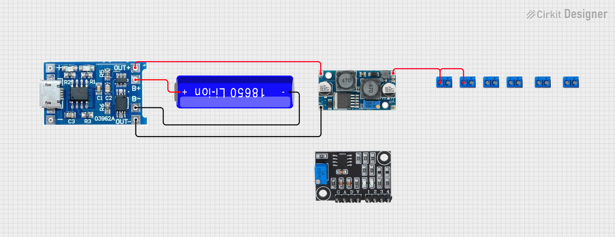 Open Project in Cirkit Designer
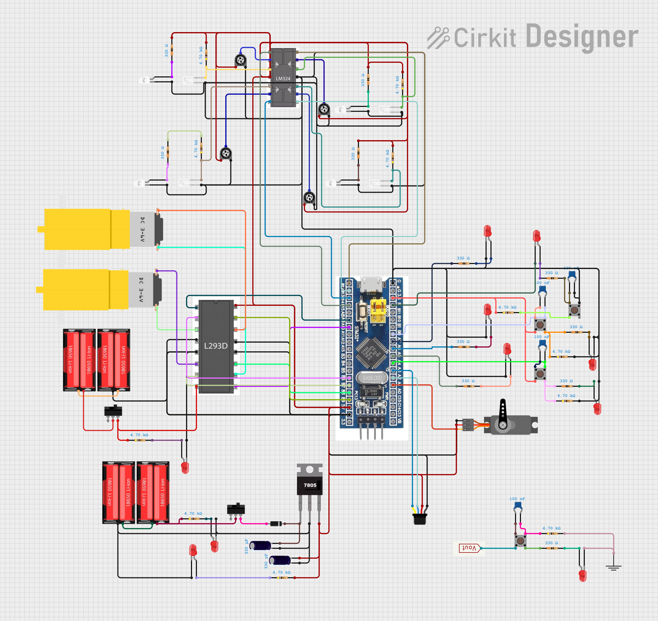 Open Project in Cirkit Designer
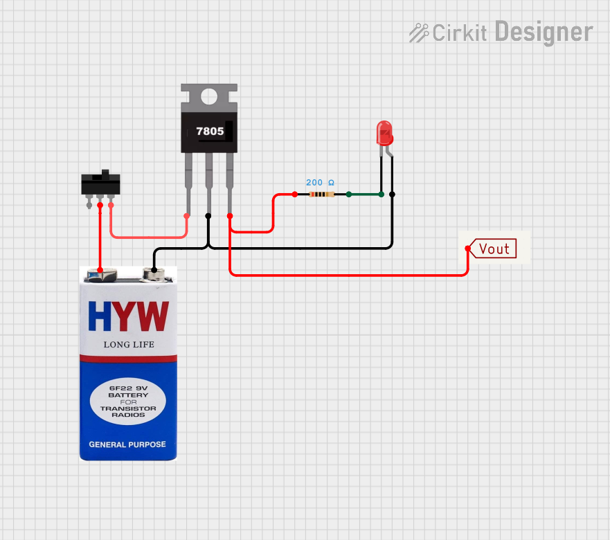 Open Project in Cirkit Designer
Explore Projects Built with V_REG_LD1085
Open Project in Cirkit DesignerOpen Project in Cirkit DesignerOpen Project in Cirkit DesignerOpen Project in Cirkit DesignerCommon Applications:
- Power supply circuits for microcontrollers (e.g., Arduino, Raspberry Pi)
- Voltage regulation in battery-powered devices
- Linear voltage regulation for sensitive analog circuits
- Post-regulation for switching power supplies
- Industrial and consumer electronics
Technical Specifications
Key Specifications:
| Parameter | Value |
|---|---|
| Output Voltage Range | 1.25V to 15V |
| Maximum Output Current | 3A |
| Dropout Voltage | 1.1V (at 3A load) |
| Input Voltage Range | Up to 30V |
| Output Voltage Tolerance | ±1% |
| Quiescent Current | 5mA (typical) |
| Operating Temperature | -40°C to +125°C |
| Package Types | TO-220, D²PAK, DPAK |
Pin Configuration:
The LD1085 is typically available in a 3-pin TO-220 package. Below is the pinout description:
| Pin Number | Pin Name | Description |
|---|---|---|
| 1 | ADJ/GND | Adjustable pin (for variable output) or Ground (for fixed output) |
| 2 | OUT | Regulated output voltage |
| 3 | IN | Input voltage |
Usage Instructions
How to Use the LD1085 in a Circuit:
- Input Voltage Requirements: Ensure the input voltage is at least 1.1V higher than the desired output voltage to maintain proper regulation.
- Output Voltage Configuration:
- For fixed output versions, connect the ADJ/GND pin directly to ground.
- For adjustable output versions, use a resistor divider network between the ADJ pin and the output to set the desired voltage. The output voltage is calculated using the formula: [ V_{OUT} = V_{REF} \times \left(1 + \frac{R_2}{R_1}\right) + I_{ADJ} \times R_2 ] where ( V_{REF} ) is typically 1.25V, and ( I_{ADJ} ) is negligible (around 50µA).
- Capacitor Selection:
- Place a 10µF capacitor on the input pin to stabilize the input voltage.
- Place a 22µF capacitor on the output pin to ensure stable operation and reduce noise.
- Thermal Management: If the regulator is dissipating significant power, attach a heatsink to the TO-220 package to prevent overheating.
Example Circuit:
Below is an example of using the LD1085 to regulate a 12V input to a 5V output:
Input Voltage (12V) ----+---- IN (Pin 3)
                        |
                     10µF
                        |
                       GND

OUT (Pin 2) ----+---- Regulated 5V Output
                |
             22µF
                |
               GND

ADJ/GND (Pin 1) ---- Resistor Divider Network (for adjustable version)
Using LD1085 with Arduino UNO:
The LD1085 can be used to power an Arduino UNO by regulating a 12V input to 5V. Connect the regulated 5V output to the Arduino's 5V pin.
Example Code for Arduino:
// Example: Reading a sensor powered by LD1085-regulated 5V
// Ensure the LD1085 output is connected to the Arduino's 5V pin.

const int sensorPin = A0; // Analog pin connected to the sensor
int sensorValue = 0;      // Variable to store the sensor reading

void setup() {
  Serial.begin(9600); // Initialize serial communication
}

void loop() {
  sensorValue = analogRead(sensorPin); // Read the sensor value
  Serial.print("Sensor Value: ");
  Serial.println(sensorValue); // Print the sensor value to the Serial Monitor
  delay(1000); // Wait for 1 second before the next reading
}
Important Considerations:
- Always use appropriate capacitors on the input and output pins to ensure stability.
- Avoid exceeding the maximum input voltage (30V) or output current (3A).
- Use a heatsink if the power dissipation exceeds safe limits.
Troubleshooting and FAQs
Common Issues and Solutions:
Output Voltage is Unstable:
- Ensure proper capacitors are connected to the input and output pins.
- Verify that the input voltage is at least 1.1V higher than the desired output voltage.
Regulator Overheats:
- Check if the load current exceeds 3A.
- Attach a heatsink to the LD1085 to improve thermal dissipation.
No Output Voltage:
- Verify all connections, especially the input and ground pins.
- Check if the input voltage is within the specified range.
Incorrect Output Voltage:
- For adjustable versions, ensure the resistor divider network is correctly calculated.
- Measure the resistors to confirm their values.
FAQs:
Q1: Can I use the LD1085 without a heatsink?
A1: Yes, but only if the power dissipation is low. For higher loads, a heatsink is necessary to prevent overheating.
Q2: What is the minimum dropout voltage of the LD1085?
A2: The dropout voltage is typically 1.1V at a 3A load. It decreases at lower currents.
Q3: Can I use the LD1085 to power a 3.3V device?
A3: Yes, but ensure the input voltage is at least 4.4V (3.3V + 1.1V dropout).
Q4: What happens if I don't use capacitors on the input and output?
A4: The regulator may become unstable, leading to oscillations or noise in the output voltage.
By following this documentation, you can effectively use the LD1085 in your electronic projects for reliable voltage regulation.