Cirkit Designer Logo
Cirkit Designer
Your all-in-one circuit design IDE
Home / 
Component Documentation

How to Use USB male 2 pin connection: Examples, Pinouts, and Specs

Image of USB male 2 pin connection
Cirkit Designer LogoDesign with USB male 2 pin connection in Cirkit Designer

Introduction

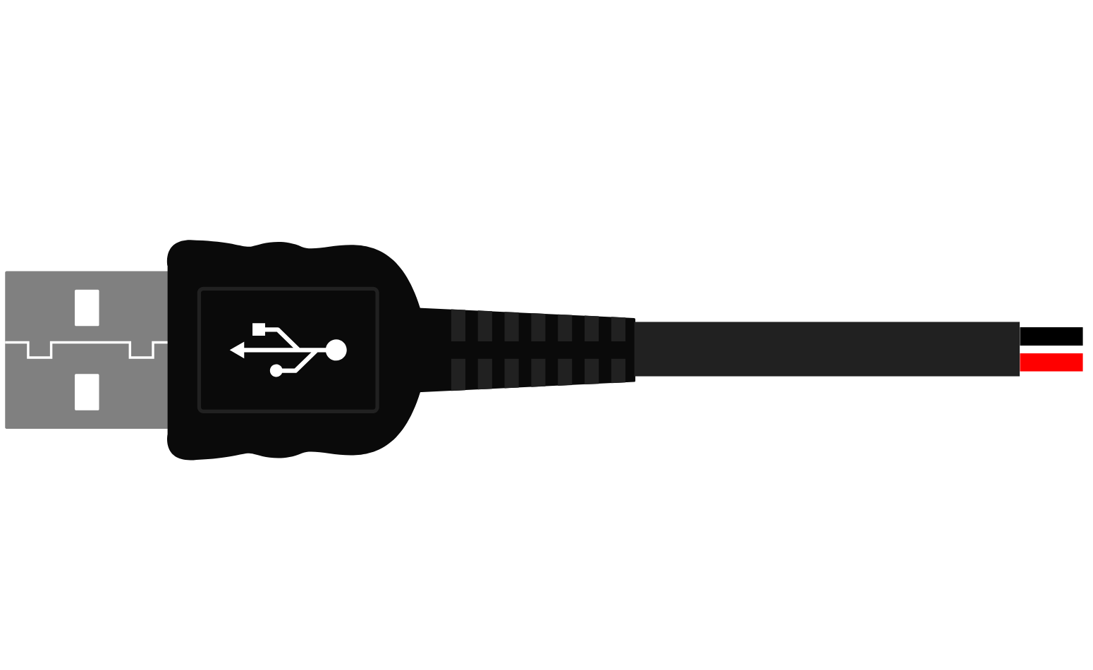
A USB male 2 pin connection is a type of electrical connector used to establish a power and data link between devices. It is commonly used in applications where only power transmission or basic data communication is required. This connector features two pins: one for power (VCC) and the other for ground (GND). Its compact design makes it ideal for connecting peripherals to computers, chargers, or other electronic devices.

Explore Projects Built with USB male 2 pin connection

Use Cirkit Designer to design, explore, and prototype these projects online. Some projects support real-time simulation. Click "Open Project" to start designing instantly!
USB-Powered Pushbutton Controlled LED Circuit
Image of oppgv. 10: A project utilizing USB male 2 pin connection in a practical application
This circuit consists of a USB power converter supplying power to three pushbuttons, each connected to a corresponding red LED. When a button is pressed, it closes the circuit for its associated LED, causing the LED to light up. The common ground for the circuit is provided through a 40-pin connector, which also serves as an interface for the pushbuttons' inputs and the LEDs' cathodes.
Cirkit Designer LogoOpen Project in Cirkit Designer
Pushbutton-Controlled Interface with 40-Pin Connector and UBS Power Supply
Image of connect 4: A project utilizing USB male 2 pin connection in a practical application
This circuit consists of a 40-pin connector interfacing with four pushbuttons and a UBS power supply. The pushbuttons are used as inputs to the connector, which then relays the signals to other components or systems. The UBS power supply provides the necessary 24V power to the pushbuttons and the common ground for the circuit.
Cirkit Designer LogoOpen Project in Cirkit Designer
USB Type-C Powered LED Circuit with Resistor
Image of Scheme1: A project utilizing USB male 2 pin connection in a practical application
This circuit consists of a USB Type-C port providing power to a red LED through a 1000 Ohm resistor. The resistor limits the current flowing through the LED, which lights up when the circuit is powered.
Cirkit Designer LogoOpen Project in Cirkit Designer
5-Pin Connector Synchronization Circuit
Image of UMB_Cable: A project utilizing USB male 2 pin connection in a practical application
This circuit consists of four 5-pin connectors, where two of the connectors are fully interconnected pin-to-pin. The purpose of this setup could be to create a parallel connection between the two 5-pin connectors, possibly for signal distribution or redundancy.
Cirkit Designer LogoOpen Project in Cirkit Designer

Explore Projects Built with USB male 2 pin connection

Use Cirkit Designer to design, explore, and prototype these projects online. Some projects support real-time simulation. Click "Open Project" to start designing instantly!
Image of oppgv. 10: A project utilizing USB male 2 pin connection in a practical application
USB-Powered Pushbutton Controlled LED Circuit
This circuit consists of a USB power converter supplying power to three pushbuttons, each connected to a corresponding red LED. When a button is pressed, it closes the circuit for its associated LED, causing the LED to light up. The common ground for the circuit is provided through a 40-pin connector, which also serves as an interface for the pushbuttons' inputs and the LEDs' cathodes.
Cirkit Designer LogoOpen Project in Cirkit Designer
Image of connect 4: A project utilizing USB male 2 pin connection in a practical application
Pushbutton-Controlled Interface with 40-Pin Connector and UBS Power Supply
This circuit consists of a 40-pin connector interfacing with four pushbuttons and a UBS power supply. The pushbuttons are used as inputs to the connector, which then relays the signals to other components or systems. The UBS power supply provides the necessary 24V power to the pushbuttons and the common ground for the circuit.
Cirkit Designer LogoOpen Project in Cirkit Designer
Image of Scheme1: A project utilizing USB male 2 pin connection in a practical application
USB Type-C Powered LED Circuit with Resistor
This circuit consists of a USB Type-C port providing power to a red LED through a 1000 Ohm resistor. The resistor limits the current flowing through the LED, which lights up when the circuit is powered.
Cirkit Designer LogoOpen Project in Cirkit Designer
Image of UMB_Cable: A project utilizing USB male 2 pin connection in a practical application
5-Pin Connector Synchronization Circuit
This circuit consists of four 5-pin connectors, where two of the connectors are fully interconnected pin-to-pin. The purpose of this setup could be to create a parallel connection between the two 5-pin connectors, possibly for signal distribution or redundancy.
Cirkit Designer LogoOpen Project in Cirkit Designer

Common Applications and Use Cases

  • Powering small electronic devices (e.g., LED strips, sensors)
  • Charging devices such as smartphones or portable gadgets
  • Basic data communication in low-power applications
  • DIY electronics projects and prototyping

Technical Specifications

Below are the key technical details for the USB male 2 pin connection:

Parameter Specification
Connector Type USB Male
Number of Pins 2
Voltage Rating 5V DC (standard USB power)
Current Rating Up to 2A (depending on cable quality)
Pin Material Copper alloy (gold or nickel plated)
Housing Material Plastic (typically ABS or PVC)
Operating Temperature -20°C to 70°C

Pin Configuration and Descriptions

The USB male 2 pin connector has the following pin configuration:

Pin Number Name Description
1 VCC Power supply (5V DC)
2 GND Ground connection

Usage Instructions

How to Use the Component in a Circuit

  1. Identify the Pins: Locate the VCC and GND pins on the USB male 2 pin connector.
  2. Connect to Power Source:
    • Connect the VCC pin to the positive terminal of your power source (e.g., 5V DC).
    • Connect the GND pin to the ground terminal of your circuit.
  3. Secure the Connection: Use soldering or a reliable connector to ensure a stable connection.
  4. Test the Circuit: Verify the voltage and current levels before powering your device.

Important Considerations and Best Practices

  • Voltage Compatibility: Ensure the connected device operates at 5V DC to avoid damage.
  • Current Rating: Do not exceed the current rating of the connector (typically 2A).
  • Cable Quality: Use high-quality cables to minimize voltage drops and ensure reliable performance.
  • Polarity Check: Double-check the polarity of the connections to prevent short circuits.
  • Insulation: Properly insulate the connections to avoid accidental shorts.

Example: Connecting to an Arduino UNO

The USB male 2 pin connection can be used to power an Arduino UNO. Below is an example of how to connect it:

  1. Connect the VCC pin of the USB connector to the 5V pin on the Arduino UNO.
  2. Connect the GND pin of the USB connector to the GND pin on the Arduino UNO.

Here is a simple Arduino sketch to blink an LED when powered via the USB male 2 pin connection:

// Simple LED Blink Example
// This code blinks an LED connected to pin 13 of the Arduino UNO.
// Ensure the Arduino is powered via the USB male 2 pin connection.

void setup() {
  pinMode(13, OUTPUT); // Set pin 13 as an output
}

void loop() {
  digitalWrite(13, HIGH); // Turn the LED on
  delay(1000);            // Wait for 1 second
  digitalWrite(13, LOW);  // Turn the LED off
  delay(1000);            // Wait for 1 second
}

Troubleshooting and FAQs

Common Issues Users Might Face

  1. No Power Output:

    • Cause: Loose or incorrect connections.
    • Solution: Check the soldering or connector for proper contact. Verify polarity.
  2. Device Not Working:

    • Cause: Voltage or current mismatch.
    • Solution: Ensure the device operates at 5V DC and does not exceed the current rating.
  3. Overheating:

    • Cause: Excessive current draw or poor cable quality.
    • Solution: Use a cable with appropriate current capacity and ensure proper ventilation.
  4. Short Circuit:

    • Cause: Exposed wires or incorrect connections.
    • Solution: Insulate all connections and double-check the wiring.

Solutions and Tips for Troubleshooting

  • Use a multimeter to verify voltage and continuity.
  • Test the USB male 2 pin connection with a known working device to isolate issues.
  • Replace damaged connectors or cables to ensure reliable performance.

By following this documentation, you can effectively use the USB male 2 pin connection in your projects and troubleshoot common issues with ease.