How to Use Zelio Smart Relay: Examples, Pinouts, and Specs
Introduction
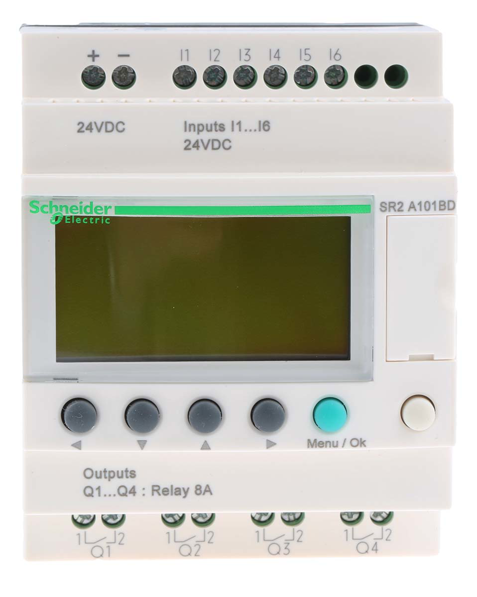
The Zelio Smart Relay (SR2 A101BD), manufactured by Schneider Electric, is a versatile and compact relay designed for automation and control applications. It is ideal for managing and monitoring electrical circuits in industrial, commercial, and residential environments. With its user-friendly interface and programmable logic capabilities, the Zelio Smart Relay simplifies complex control tasks, making it a popular choice for engineers and technicians.
Explore Projects Built with Zelio Smart Relay


Explore Projects Built with Zelio Smart Relay
Common Applications and Use Cases
- Industrial automation and process control
- Building management systems (e.g., lighting, HVAC control)
- Remote monitoring and control of electrical circuits
- Small-scale machine automation
- Home automation projects
Technical Specifications
The Zelio Smart Relay offers robust performance and flexibility. Below are its key technical details:
General Specifications
| Parameter | Value |
|---|---|
| Manufacturer | Schneider Electric |
| Part Number | SR2 A101BD |
| Supply Voltage | 12 V DC |
| Input Voltage Range | 10.2 V to 14.4 V DC |
| Number of Inputs | 6 |
| Number of Outputs | 4 relay outputs |
| Output Type | Relay (SPDT) |
| Maximum Output Current | 8 A per relay |
| Programming Interface | Zelio Soft software |
| Display | LCD with 4 lines, 18 characters per line |
| Operating Temperature | -20°C to +55°C |
| Dimensions (HxWxD) | 90 x 70 x 59 mm |
| Mounting Type | DIN rail or panel mount |
Pin Configuration and Descriptions
The Zelio Smart Relay features a terminal block for connecting inputs, outputs, and power. Below is the pin configuration:
Input Terminals
| Pin Number | Description | Notes |
|---|---|---|
| I1 | Digital Input 1 | Accepts 12 V DC signals |
| I2 | Digital Input 2 | Accepts 12 V DC signals |
| I3 | Digital Input 3 | Accepts 12 V DC signals |
| I4 | Digital Input 4 | Accepts 12 V DC signals |
| I5 | Digital Input 5 | Accepts 12 V DC signals |
| I6 | Digital Input 6 | Accepts 12 V DC signals |
Output Terminals
| Pin Number | Description | Notes |
|---|---|---|
| Q1 | Relay Output 1 (SPDT) | Max 8 A |
| Q2 | Relay Output 2 (SPDT) | Max 8 A |
| Q3 | Relay Output 3 (SPDT) | Max 8 A |
| Q4 | Relay Output 4 (SPDT) | Max 8 A |
Power Terminals
| Pin Number | Description | Notes |
|---|---|---|
| + | Positive Power Supply | Connect to 12 V DC |
| - | Negative Power Supply | Connect to ground |
Usage Instructions
The Zelio Smart Relay is designed for ease of use in a variety of applications. Follow the steps below to integrate it into your circuit:
Step 1: Power Connection
- Connect the + terminal to a 12 V DC power source.
- Connect the - terminal to the ground of the power source.
Step 2: Input Connections
- Connect digital input signals (e.g., switches, sensors) to the input terminals (I1 to I6). Ensure the input voltage is within the specified range (10.2 V to 14.4 V DC).
Step 3: Output Connections
- Connect the devices you want to control (e.g., motors, lights) to the output terminals (Q1 to Q4). Ensure the load does not exceed the maximum current rating of 8 A per relay.
Step 4: Programming
- Use the Zelio Soft software to program the relay. The software provides a graphical interface for creating logic diagrams and configuring the relay's behavior.
- Connect the relay to your computer via the programming cable and upload your program.
Step 5: Testing
- Power on the relay and verify that the inputs and outputs function as expected based on your program.
Example: Connecting to an Arduino UNO
The Zelio Smart Relay can be controlled by an Arduino UNO for advanced automation tasks. Below is an example code snippet to toggle an output relay based on an Arduino digital pin:
// Example: Controlling Zelio Smart Relay with Arduino UNO
// This code toggles Relay Output Q1 based on a button press

const int buttonPin = 2;  // Button connected to digital pin 2
const int relayPin = 3;   // Relay control connected to digital pin 3

void setup() {
  pinMode(buttonPin, INPUT_PULLUP); // Configure button pin as input with pull-up
  pinMode(relayPin, OUTPUT);       // Configure relay pin as output
  digitalWrite(relayPin, LOW);     // Ensure relay is off initially
}

void loop() {
  int buttonState = digitalRead(buttonPin); // Read button state

  if (buttonState == LOW) { // Button pressed (active low)
    digitalWrite(relayPin, HIGH); // Turn on relay
  } else {
    digitalWrite(relayPin, LOW);  // Turn off relay
  }
}
Important Considerations
- Ensure the relay is powered within the specified voltage range to avoid damage.
- Avoid exceeding the maximum current rating of 8 A per relay output.
- Use proper insulation and wiring practices to ensure safety and reliability.
- For inductive loads (e.g., motors), use a flyback diode to protect the relay from voltage spikes.
Troubleshooting and FAQs
Common Issues and Solutions
Relay does not power on:
- Verify the power supply voltage is within the range of 10.2 V to 14.4 V DC.
- Check the wiring connections to the + and - terminals.
Inputs not responding:
- Ensure the input voltage is within the specified range.
- Check for loose or incorrect wiring connections.
Outputs not activating:
- Verify the load connected to the output does not exceed the maximum current rating.
- Check the program logic in the Zelio Soft software.
Relay behaves erratically:
- Ensure the power supply is stable and free from noise.
- Check for electromagnetic interference (EMI) near the relay.
FAQs
Q: Can the Zelio Smart Relay be used with AC loads?
A: Yes, the relay outputs can control AC loads, but ensure the load current does not exceed 8 A.
Q: Is the Zelio Soft software free?
A: Yes, the Zelio Soft software is available for free download from Schneider Electric's website.
Q: Can the relay be programmed without a computer?
A: Yes, the relay can be programmed using its built-in LCD and buttons, but the Zelio Soft software provides a more user-friendly interface.
Q: What is the lifespan of the relay?
A: The relay is rated for a mechanical lifespan of up to 10 million operations under normal conditions.