Cirkit Designer Logo
Cirkit Designer
Your all-in-one circuit design IDE
Home / 
Component Documentation

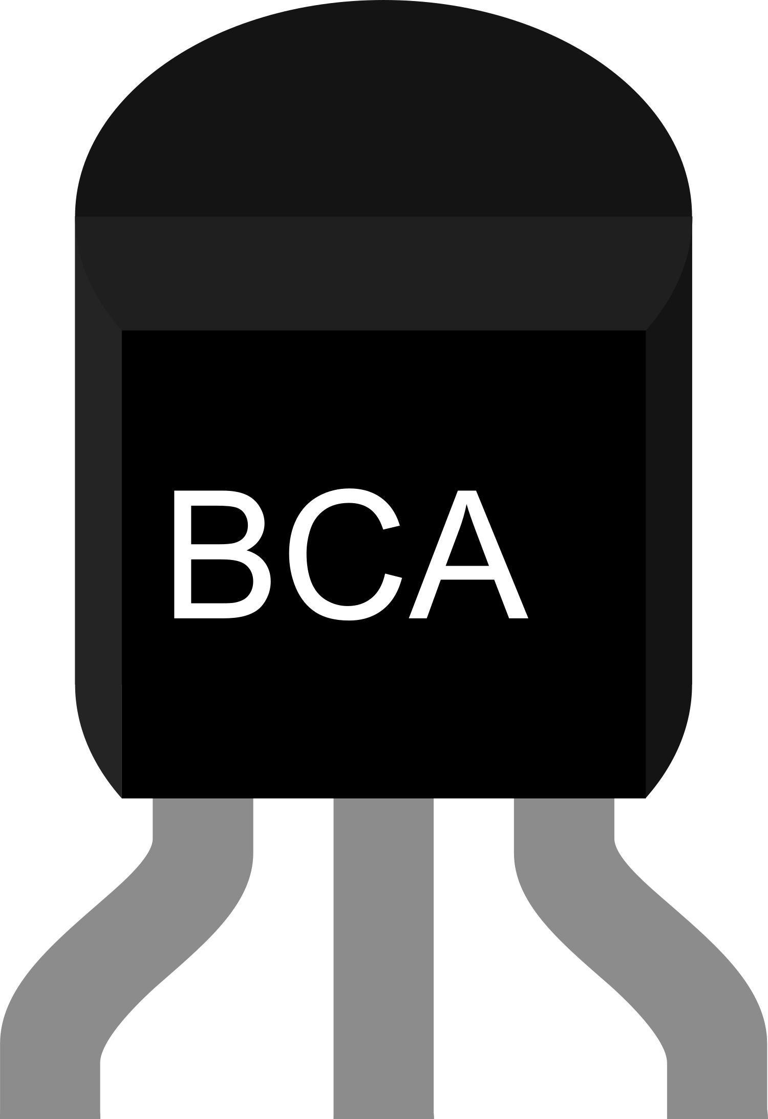
How to Use NPN-Transistor: Examples, Pinouts, and Specs

Image of NPN-Transistor
Cirkit Designer LogoDesign with NPN-Transistor in Cirkit Designer

Introduction

An NPN transistor is a fundamental electronic component used in various applications to amplify or switch electronic signals. It is a type of bipolar junction transistor (BJT) that consists of three layers of semiconductor material, with the order being N-type, P-type, and N-type. The NPN transistor is widely used in digital and analog circuits due to its high current and voltage handling capabilities, fast switching, and ease of integration.

Explore Projects Built with NPN-Transistor

Use Cirkit Designer to design, explore, and prototype these projects online. Some projects support real-time simulation. Click "Open Project" to start designing instantly!
NPN Transistor-Based Voltage Measurement Circuit with Dual Power Supplies
Image of lab9: A project utilizing NPN-Transistor in a practical application
This circuit is a simple NPN transistor switch configuration powered by two power supplies. It includes resistors to limit current and multimeters to measure voltage and current at various points in the circuit.
Cirkit Designer LogoOpen Project in Cirkit Designer
NPN Transistor-Based Signal Interface with Relimate Connectors
Image of Mini cross: A project utilizing NPN-Transistor in a practical application
This circuit appears to be a simple transistor-based switching circuit with multiple NPN transistors and resistors, interfaced through relimate connectors. The transistors are likely used to control the flow of current through various parts of the circuit, possibly for switching or amplification purposes, with the relimate connectors providing external connections for power and signal lines.
Cirkit Designer LogoOpen Project in Cirkit Designer
Transistor-Based LED Driver Circuit with Capacitive Filtering
Image of testing: A project utilizing NPN-Transistor in a practical application
This circuit is an analog LED driver that uses a PNP transistor to switch an LED on and off. An NPN transistor is used to control the PNP transistor, and various resistors and capacitors are used to bias the transistors and filter noise. The circuit is powered by a single AA battery.
Cirkit Designer LogoOpen Project in Cirkit Designer
Transistor-Based Signal Modulation Circuit with AC/DC Power Integration
Image of PPPPP: A project utilizing NPN-Transistor in a practical application
This circuit appears to be a transistor-based switching or amplification system powered by a 12v battery, with an AC supply possibly for signal input or additional power. It includes filtering through ceramic capacitors and uses resistors for biasing the transistors. The presence of both PNP and NPN transistors suggests a push-pull configuration or a form of signal modulation.
Cirkit Designer LogoOpen Project in Cirkit Designer

Explore Projects Built with NPN-Transistor

Use Cirkit Designer to design, explore, and prototype these projects online. Some projects support real-time simulation. Click "Open Project" to start designing instantly!
Image of lab9: A project utilizing NPN-Transistor in a practical application
NPN Transistor-Based Voltage Measurement Circuit with Dual Power Supplies
This circuit is a simple NPN transistor switch configuration powered by two power supplies. It includes resistors to limit current and multimeters to measure voltage and current at various points in the circuit.
Cirkit Designer LogoOpen Project in Cirkit Designer
Image of Mini cross: A project utilizing NPN-Transistor in a practical application
NPN Transistor-Based Signal Interface with Relimate Connectors
This circuit appears to be a simple transistor-based switching circuit with multiple NPN transistors and resistors, interfaced through relimate connectors. The transistors are likely used to control the flow of current through various parts of the circuit, possibly for switching or amplification purposes, with the relimate connectors providing external connections for power and signal lines.
Cirkit Designer LogoOpen Project in Cirkit Designer
Image of testing: A project utilizing NPN-Transistor in a practical application
Transistor-Based LED Driver Circuit with Capacitive Filtering
This circuit is an analog LED driver that uses a PNP transistor to switch an LED on and off. An NPN transistor is used to control the PNP transistor, and various resistors and capacitors are used to bias the transistors and filter noise. The circuit is powered by a single AA battery.
Cirkit Designer LogoOpen Project in Cirkit Designer
Image of PPPPP: A project utilizing NPN-Transistor in a practical application
Transistor-Based Signal Modulation Circuit with AC/DC Power Integration
This circuit appears to be a transistor-based switching or amplification system powered by a 12v battery, with an AC supply possibly for signal input or additional power. It includes filtering through ceramic capacitors and uses resistors for biasing the transistors. The presence of both PNP and NPN transistors suggests a push-pull configuration or a form of signal modulation.
Cirkit Designer LogoOpen Project in Cirkit Designer

Common Applications and Use Cases

  • Amplification of audio signals in radios and amplifiers
  • Switching operations in digital circuits
  • Voltage regulation in power supplies
  • Signal modulation in communication devices
  • Driving motors and other high-power loads

Technical Specifications

Key Technical Details

  • Collector-Emitter Voltage (Vce): Maximum voltage that can be applied across the collector-emitter junction.
  • Collector Current (Ic): Maximum current that can flow through the collector.
  • Base Current (Ib): Current flowing into the base terminal.
  • Power Dissipation (Pd): Maximum power the transistor can dissipate without damage.
  • Transition Frequency (ft): Frequency at which the gain of the transistor falls to 1.

Pin Configuration and Descriptions

Pin Number Name Description
1 Base Controls the transistor's operation
2 Collector Collects the current flowing through the transistor
3 Emitter Emits the current from the transistor to the ground
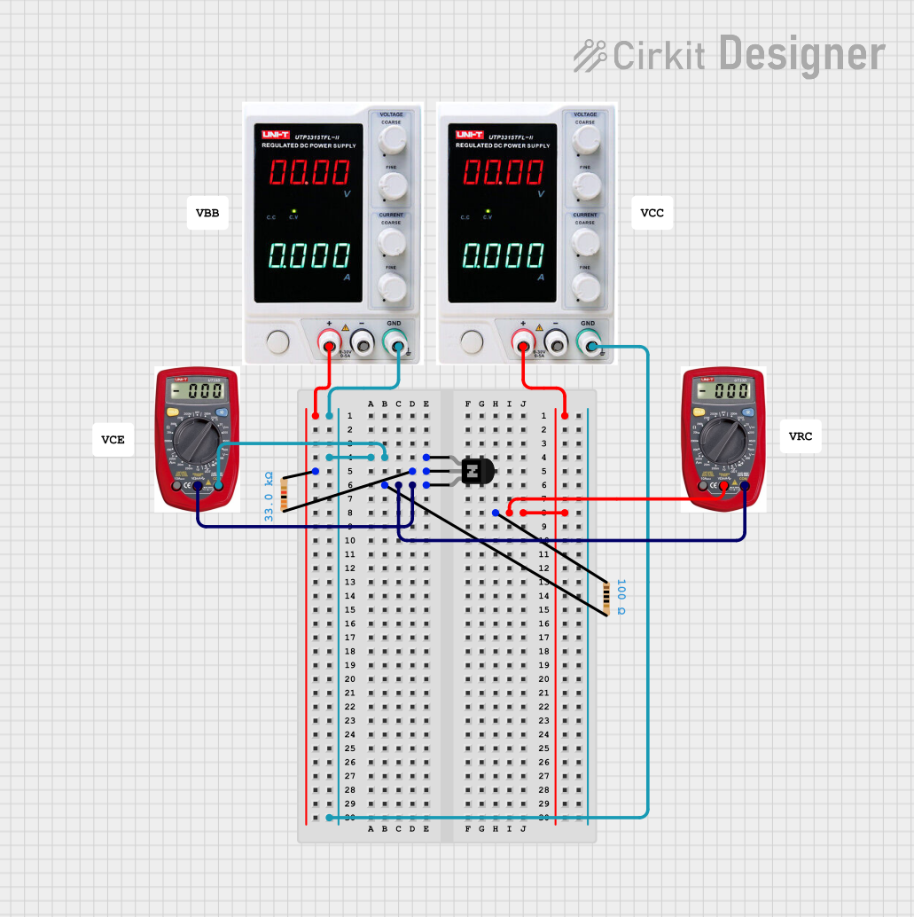
Usage Instructions

How to Use the Component in a Circuit

  1. Biasing the Transistor: Apply a small base current (Ib) to control the larger collector current (Ic).
  2. Amplifier Configuration: Connect the signal to be amplified to the base, and the load to the collector.
  3. Switch Configuration: Apply a sufficient base current to saturate the transistor, allowing maximum current to flow from collector to emitter.

Important Considerations and Best Practices

  • Ensure the transistor's maximum ratings are not exceeded to prevent damage.
  • Use a current-limiting resistor at the base to control the base current.
  • Provide adequate heat sinking if the transistor is expected to dissipate significant power.
  • When using as a switch, ensure the transistor is either fully on (saturated) or fully off (cut-off) to minimize power loss.

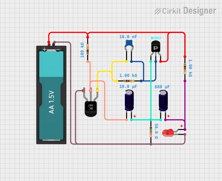
Example Circuit: NPN Transistor as a Switch

// Example code for controlling an NPN transistor connected to an Arduino UNO

const int basePin = 3; // Base pin of the NPN transistor connected to digital pin 3
const int ledPin = 13; // LED connected to the collector of the transistor

void setup() {
  pinMode(basePin, OUTPUT); // Set the transistor base pin as an output
  pinMode(ledPin, OUTPUT);  // Set the LED pin as an output
}

void loop() {
  digitalWrite(basePin, HIGH); // Turn on the transistor (LED ON)
  delay(1000);                // Wait for 1 second
  digitalWrite(basePin, LOW);  // Turn off the transistor (LED OFF)
  delay(1000);                // Wait for 1 second
}

Troubleshooting and FAQs

Common Issues Users Might Face

  • Transistor Not Switching: Check if the base current is sufficient to drive the transistor into saturation.
  • Excessive Heat: Ensure the power dissipation is within the transistor's limits and improve heat sinking if necessary.
  • Unexpected Operation: Verify the pin configuration and ensure correct connections.

Solutions and Tips for Troubleshooting

  • Use a multimeter to check for proper voltage levels at the base, collector, and emitter.
  • Replace the transistor if it shows signs of damage or if you suspect it is not functioning correctly.
  • Consult the datasheet for detailed specifications and verify that the circuit design aligns with these parameters.

FAQs

Q: Can I use an NPN transistor to control AC loads? A: NPN transistors are typically used for DC loads. For AC loads, consider using a relay or a TRIAC.

Q: How do I calculate the base resistor value? A: The base resistor value can be calculated using Ohm's law, considering the desired base current and the voltage drop from the control signal to the base-emitter voltage.

Q: What happens if I reverse the collector and emitter? A: The transistor will not function correctly as it is not symmetrical. The collector and emitter have different doping levels and are designed for specific roles.

This documentation provides a comprehensive guide to using an NPN transistor in electronic circuits. For further information, always refer to the specific datasheet of the transistor model you are using.