
How to Use ADXRSXXX: Examples, Pinouts, and Specs
 Design with ADXRSXXX in Cirkit Designer
Introduction
The ADXRSXXX is a family of high-performance MEMS (Micro-Electro-Mechanical Systems) gyroscopes designed for precise angular rate sensing. These gyroscopes are widely used in applications such as motion tracking, stabilization, and navigation systems. With their low noise, high reliability, and robust design, the ADXRSXXX series is ideal for demanding environments and applications requiring accurate rotational measurements.
Explore Projects Built with ADXRSXXX
 Open Project in Cirkit Designer
 Open Project in Cirkit Designer
 Open Project in Cirkit Designer
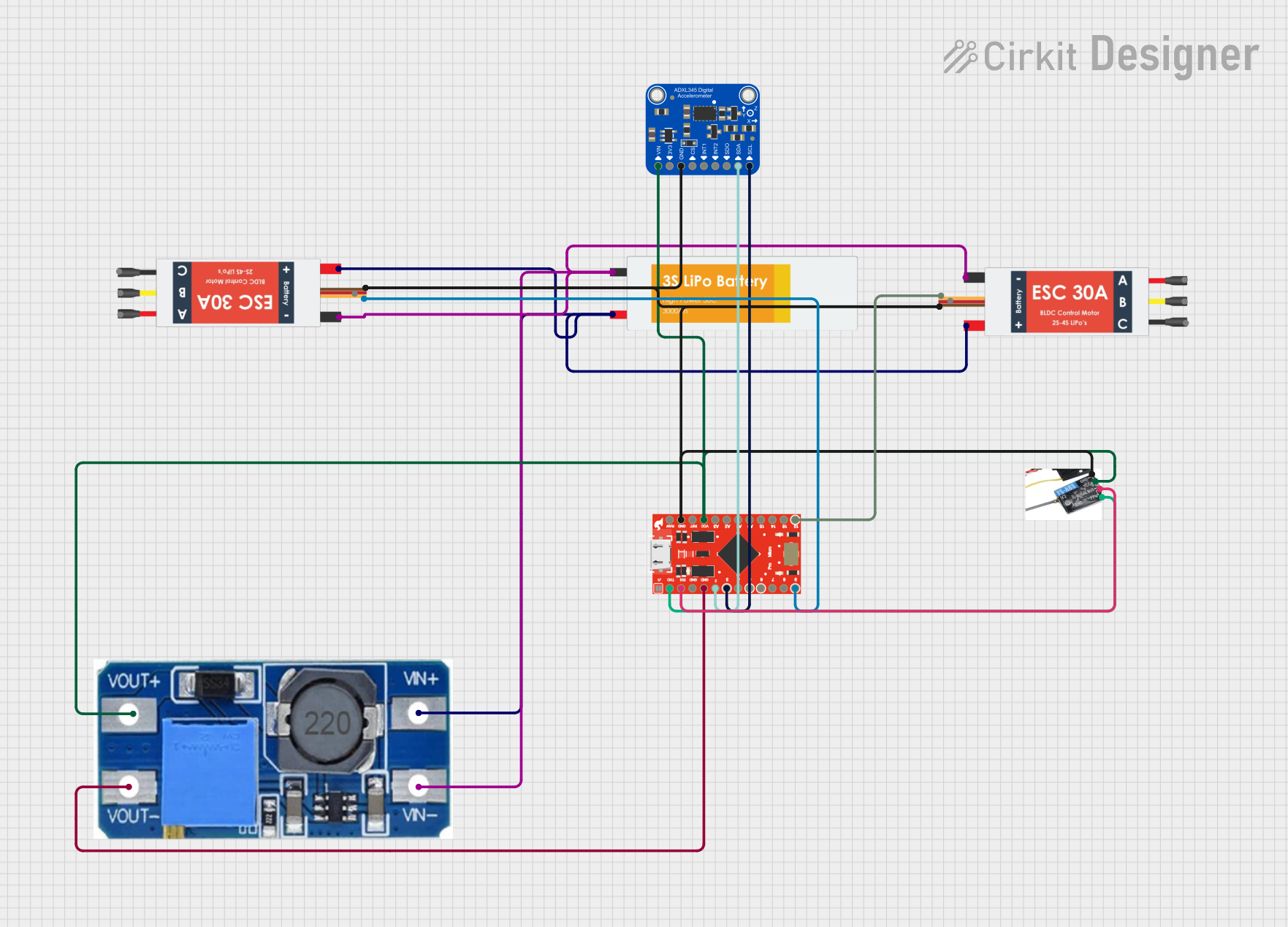 Open Project in Cirkit Designer
Explore Projects Built with ADXRSXXX
Open Project in Cirkit DesignerOpen Project in Cirkit DesignerOpen Project in Cirkit DesignerOpen Project in Cirkit DesignerCommon Applications:
- Motion tracking in robotics and drones
- Stabilization systems for cameras and vehicles
- Navigation systems in aerospace and automotive industries
- Industrial equipment monitoring and control
Technical Specifications
The ADXRSXXX family offers a range of models with varying specifications. Below are the general technical details for the series:
| Parameter | Value |
|---|---|
| Supply Voltage (Vdd) | 3.3V to 5.0V |
| Angular Rate Range | ±250°/s to ±2000°/s (model-dependent) |
| Sensitivity | 12.5 mV/°/s to 5 mV/°/s |
| Noise Density | 0.02°/s/√Hz |
| Operating Temperature | -40°C to +85°C |
| Power Consumption | 3 mA to 6 mA |
| Output Type | Analog Voltage |
| Bandwidth | Configurable, up to 100 Hz |
Pin Configuration and Descriptions
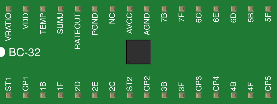
The ADXRSXXX gyroscope typically comes in a compact surface-mount package. Below is the pinout for a standard model in the series:
| Pin Number | Pin Name | Description |
|---|---|---|
| 1 | Vdd | Power supply input (3.3V to 5.0V) |
| 2 | GND | Ground |
| 3 | RATEOUT | Analog output proportional to angular rate |
| 4 | ST | Self-test input (activates self-test mode) |
| 5 | TEMP | Temperature sensor output (analog voltage) |
| 6 | NC | No connection (leave unconnected) |
| 7 | CP1 | Charge pump capacitor connection 1 |
| 8 | CP2 | Charge pump capacitor connection 2 |
Note: Refer to the specific datasheet of your ADXRSXXX model for exact pin configurations and additional details.
Usage Instructions
How to Use the ADXRSXXX in a Circuit
- Power Supply: Connect the Vdd pin to a stable 3.3V or 5.0V power source, and connect the GND pin to the ground of your circuit.
- Angular Rate Output: The RATEOUT pin provides an analog voltage proportional to the angular rate. Use an ADC (Analog-to-Digital Converter) to read this value if interfacing with a microcontroller.
- Temperature Output: The TEMP pin outputs an analog voltage corresponding to the internal temperature of the gyroscope. This can be used for temperature compensation.
- Self-Test: To verify the functionality of the gyroscope, apply a logic high signal to the ST pin. This activates the self-test mode, which generates a known output signal on the RATEOUT pin.
- Charge Pump Capacitors: Connect appropriate capacitors to the CP1 and CP2 pins as specified in the datasheet to ensure proper operation of the internal charge pump.
Important Considerations and Best Practices
- Decoupling Capacitors: Place a 0.1 µF ceramic capacitor close to the Vdd pin to filter out noise from the power supply.
- PCB Layout: Minimize vibrations and mechanical stress on the PCB to avoid interference with the gyroscope's measurements.
- Bandwidth Configuration: Use external resistors and capacitors to configure the bandwidth of the gyroscope as per your application requirements.
- Temperature Compensation: Use the TEMP output to compensate for temperature-induced drift in the angular rate measurements.
Example: Interfacing ADXRSXXX with Arduino UNO
Below is an example of how to read the RATEOUT pin using an Arduino UNO:
// Define the analog pin connected to the RATEOUT pin of ADXRSXXX
const int rateOutPin = A0;

void setup() {
  Serial.begin(9600); // Initialize serial communication at 9600 baud
}

void loop() {
  // Read the analog voltage from the RATEOUT pin
  int rateOutValue = analogRead(rateOutPin);

  // Convert the analog reading to a voltage (assuming 5V reference)
  float voltage = rateOutValue * (5.0 / 1023.0);

  // Calculate the angular rate (example sensitivity: 12.5 mV/°/s)
  float angularRate = voltage / 0.0125;

  // Print the angular rate to the Serial Monitor
  Serial.print("Angular Rate: ");
  Serial.print(angularRate);
  Serial.println(" °/s");

  delay(500); // Wait for 500 ms before the next reading
}
Note: Adjust the sensitivity value in the code based on the specific ADXRSXXX model you are using.
Troubleshooting and FAQs
Common Issues and Solutions
No Output from RATEOUT Pin:
- Ensure the Vdd and GND pins are properly connected.
- Verify that the charge pump capacitors (CP1 and CP2) are correctly installed.
Inconsistent or Noisy Measurements:
- Check for mechanical vibrations or shocks affecting the gyroscope.
- Use proper decoupling capacitors to filter power supply noise.
Incorrect Angular Rate Readings:
- Verify the sensitivity value for your specific ADXRSXXX model.
- Perform temperature compensation using the TEMP output.
Self-Test Mode Not Working:
- Ensure the ST pin is connected to a valid logic high signal.
- Check the datasheet for the expected self-test output signal.
FAQs
Q: Can I use the ADXRSXXX with a 3.3V microcontroller?
A: Yes, the ADXRSXXX supports a supply voltage range of 3.3V to 5.0V, making it compatible with 3.3V systems.
Q: How do I configure the bandwidth of the gyroscope?
A: The bandwidth can be configured using external resistors and capacitors connected to specific pins. Refer to the datasheet for detailed instructions.
Q: Is the ADXRSXXX suitable for high-vibration environments?
A: Yes, the ADXRSXXX is designed to operate reliably in high-vibration environments, but proper PCB mounting and mechanical isolation are recommended for optimal performance.
Q: Can I use multiple ADXRSXXX gyroscopes in the same system?
A: Yes, multiple gyroscopes can be used in the same system. Ensure proper power supply decoupling and signal isolation to avoid interference.
For additional support, consult the official datasheet or contact the manufacturer.