How to Use First Order Systems: Examples, Pinouts, and Specs
Introduction
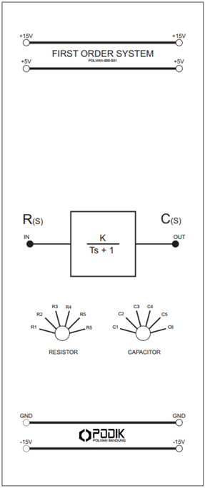
First Order Systems, manufactured by PODIK, are dynamic systems characterized by a single energy storage element. These systems are typically described by a first-order differential equation and exhibit a linear response to input signals. The defining feature of a First Order System is its time constant, which determines the speed of the system's response to changes in input.
Explore Projects Built with First Order Systems
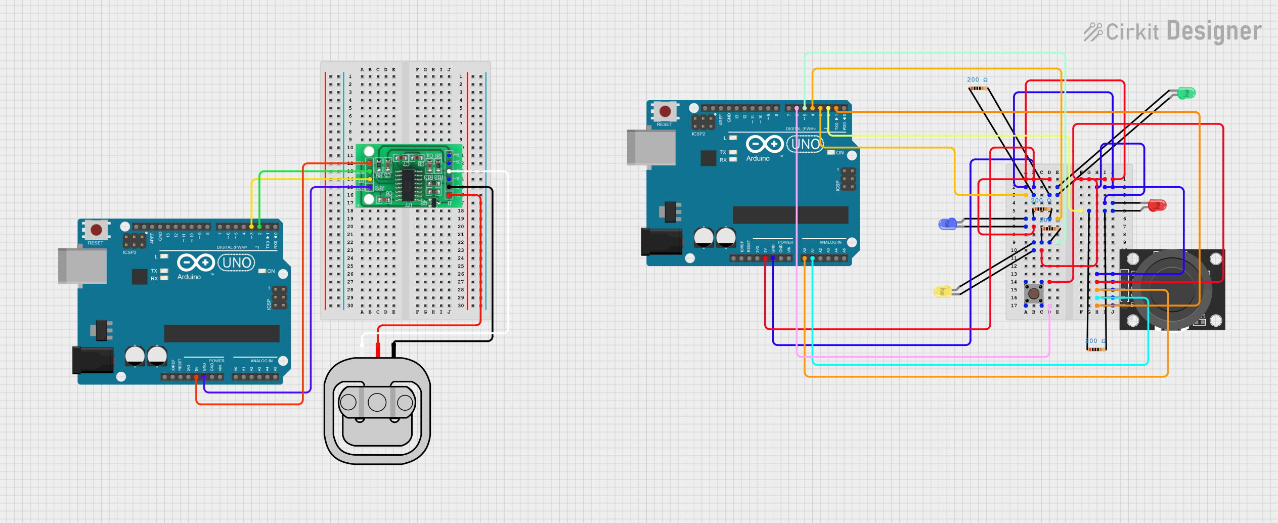
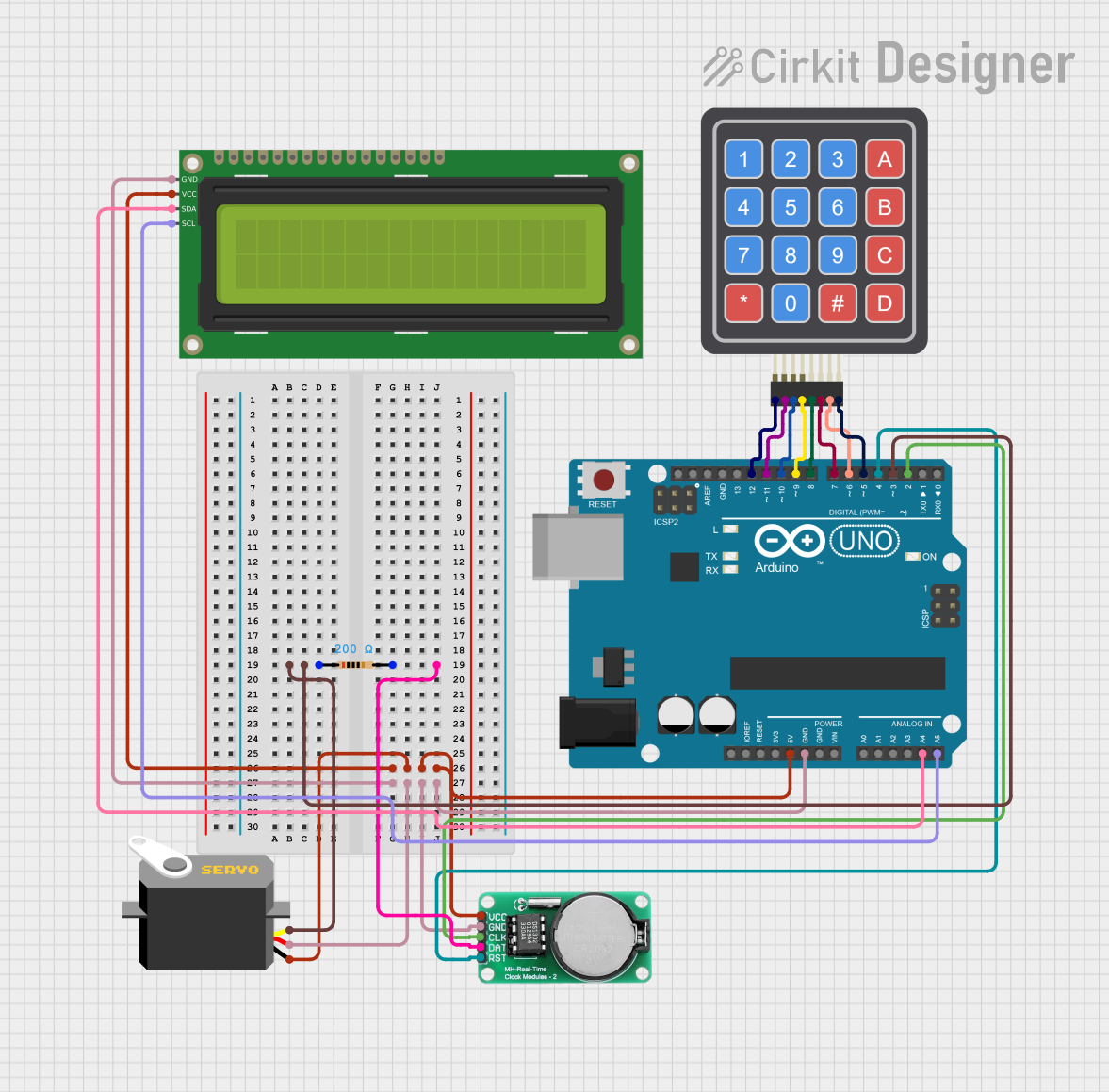
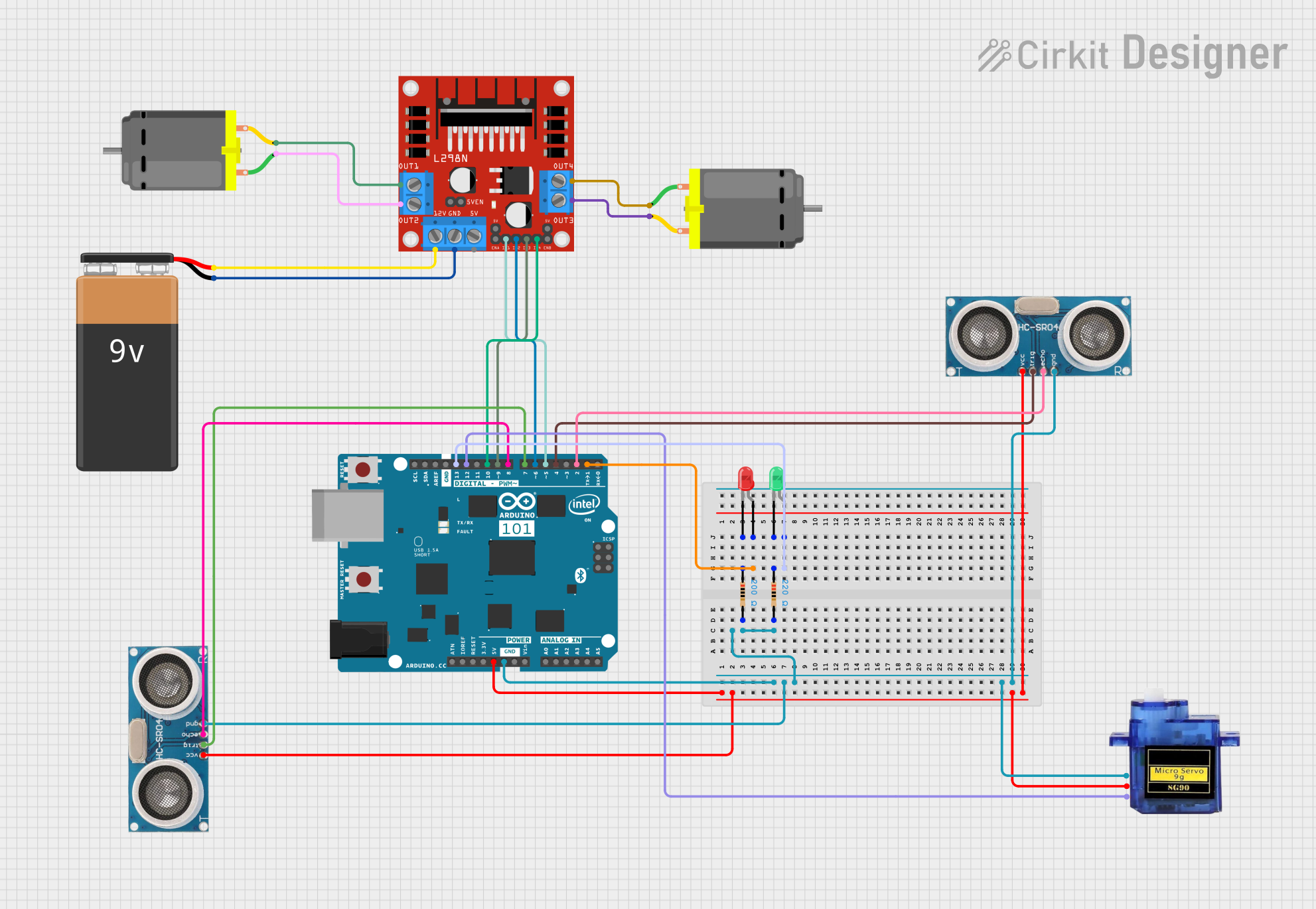
Explore Projects Built with First Order Systems
Common Applications and Use Cases
- Control Systems: Used in proportional-integral-derivative (PID) controllers and feedback loops.
- Signal Processing: Low-pass filters for smoothing signals.
- Thermal Systems: Modeling heat transfer in systems with a single thermal mass.
- Electrical Circuits: RC (Resistor-Capacitor) and RL (Resistor-Inductor) circuits.
- Mechanical Systems: Modeling damped mass-spring systems with negligible inertia.
Technical Specifications
Below are the key technical details for PODIK's First Order Systems:
General Specifications
| Parameter | Value/Description |
|---|---|
| System Type | Linear, time-invariant |
| Order | First-order |
| Time Constant (τ) | User-defined (depends on application) |
| Input Signal Type | Step, ramp, sinusoidal, or arbitrary |
| Output Response | Exponential (for step input) |
Pin Configuration and Descriptions
For electronic implementations of First Order Systems (e.g., RC circuits), the following table describes the typical pin configuration:
| Pin Number | Name | Description |
|---|---|---|
| 1 | Input Signal | Accepts the input signal to the system. |
| 2 | Ground (GND) | Connects to the system ground. |
| 3 | Output Signal | Provides the system's output response. |
Usage Instructions
How to Use the Component in a Circuit
- Identify the Application: Determine the purpose of the First Order System (e.g., filtering, control).
- Select Components: For an RC circuit implementation:
- Choose a resistor (R) and capacitor (C) such that the time constant τ = R × C meets your requirements.
- Connect the Circuit:
- Connect the input signal to the resistor.
- Connect the capacitor in parallel with the output.
- Ensure proper grounding for stable operation.
- Power the Circuit: If the system requires external power, ensure the voltage and current ratings are within safe limits.
Important Considerations and Best Practices
- Time Constant Selection: The time constant (τ) determines the speed of the system's response. A smaller τ results in a faster response, while a larger τ results in a slower response.
- Stability: Ensure the system is stable by avoiding component values that could lead to oscillations or instability.
- Signal Amplitude: Ensure the input signal amplitude does not exceed the system's maximum rating to avoid distortion or damage.
- Noise Filtering: Use decoupling capacitors to minimize noise in sensitive applications.
Example: Using a First Order System with Arduino UNO
Below is an example of simulating a First Order System (e.g., an RC low-pass filter) with an Arduino UNO:
// Arduino code to simulate a First Order System response
// This example reads an analog input, applies a simple low-pass filter,
// and outputs the filtered signal via PWM.

const int inputPin = A0;  // Analog input pin for the signal
const int outputPin = 9;  // PWM output pin
float alpha = 0.1;        // Filter coefficient (related to time constant)
float filteredValue = 0;  // Variable to store the filtered signal

void setup() {
  pinMode(outputPin, OUTPUT);  // Set the output pin as an output
  Serial.begin(9600);         // Initialize serial communication
}

void loop() {
  int inputValue = analogRead(inputPin);  // Read the input signal
  // Apply the low-pass filter equation
  filteredValue = alpha * inputValue + (1 - alpha) * filteredValue;

  // Map the filtered value to a PWM range (0-255)
  int pwmValue = map(filteredValue, 0, 1023, 0, 255);
  analogWrite(outputPin, pwmValue);  // Output the filtered signal

  // Print the values for debugging
  Serial.print("Input: ");
  Serial.print(inputValue);
  Serial.print(" Filtered: ");
  Serial.println(filteredValue);

  delay(10);  // Small delay for stability
}
Troubleshooting and FAQs
Common Issues Users Might Face
Slow Response Time:
- Cause: Time constant (τ) is too large.
- Solution: Reduce the resistor or capacitor value to decrease τ.
Unstable Output:
- Cause: Incorrect component values or poor grounding.
- Solution: Verify connections and ensure proper grounding.
No Output Signal:
- Cause: Input signal not connected or incorrect component placement.
- Solution: Check the input signal and verify the circuit connections.
Distorted Output:
- Cause: Input signal amplitude exceeds system limits.
- Solution: Reduce the input signal amplitude or use components with higher ratings.
FAQs
Q1: How do I calculate the time constant for my application?
A1: The time constant (τ) is calculated as τ = R × C for an RC circuit or τ = L / R for an RL circuit. Choose R, C, or L values based on the desired response speed.
Q2: Can I use a First Order System for high-frequency signals?
A2: Yes, but ensure the time constant is small enough to allow the system to respond to high-frequency changes.
Q3: What is the difference between a First Order System and a Second Order System?
A3: A First Order System has one energy storage element and an exponential response, while a Second Order System has two energy storage elements and can exhibit oscillatory behavior.
By following this documentation, users can effectively implement and troubleshoot PODIK's First Order Systems in their applications.