How to Use StamPLC: Examples, Pinouts, and Specs
Introduction
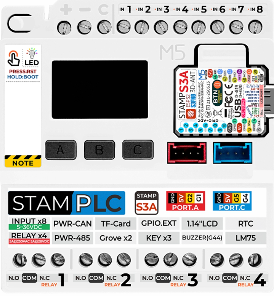
The StamPLC, manufactured by M5Stack, is a compact and versatile programmable logic controller (PLC) designed for industrial automation. It is capable of controlling machinery, processes, and systems through programmable instructions, making it an essential component for modern industrial applications. The StamPLC is designed to be user-friendly, reliable, and highly customizable, catering to a wide range of automation needs.
Explore Projects Built with StamPLC

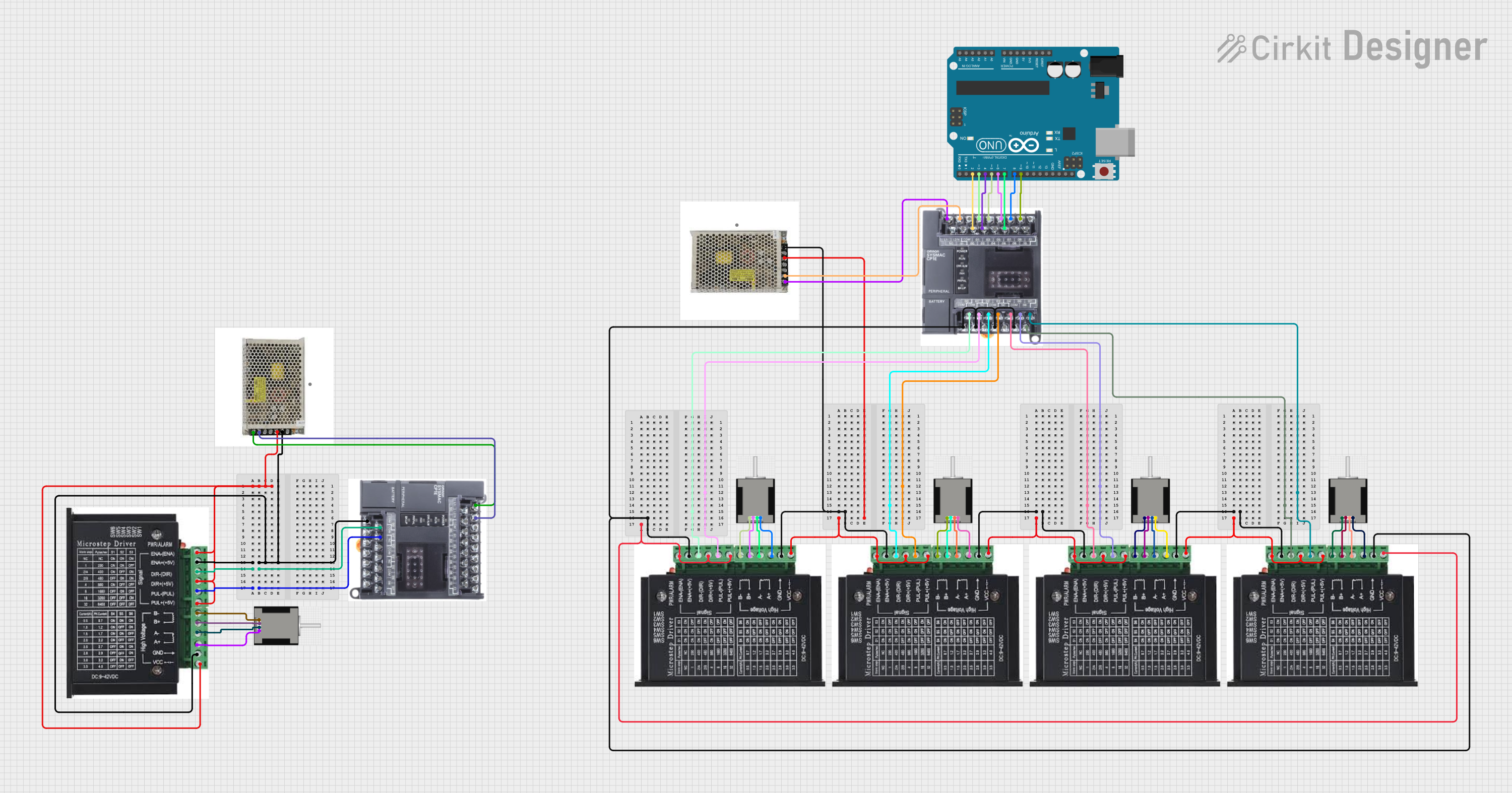
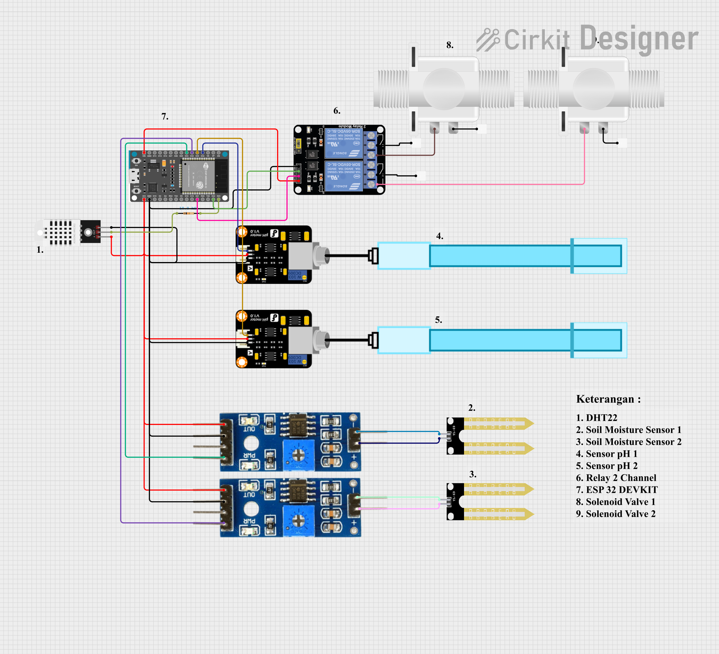

Explore Projects Built with StamPLC
Common Applications and Use Cases
- Industrial machinery control
- Process automation in manufacturing
- Building automation systems
- Conveyor belt systems
- Robotics and motion control
- Data acquisition and monitoring
Technical Specifications
The StamPLC is built to handle demanding industrial environments while maintaining ease of use. Below are its key technical specifications:
General Specifications
| Parameter | Value |
|---|---|
| Manufacturer | M5Stack |
| Operating Voltage | 5V DC |
| Input Voltage Range | 5V to 24V DC |
| Digital Inputs | 8 channels |
| Digital Outputs | 8 channels (relay-driven) |
| Communication Protocols | RS485, Modbus RTU, UART, I2C |
| CPU | ESP32 (dual-core, 240 MHz) |
| Memory | 16 MB Flash, 520 KB SRAM |
| Operating Temperature | -20°C to 70°C |
| Dimensions | 90mm x 60mm x 25mm |
Pin Configuration and Descriptions
The StamPLC features a well-labeled pinout for easy integration into circuits. Below is the pin configuration:
Input Pins
| Pin Number | Label | Description |
|---|---|---|
| 1 | IN1 | Digital Input 1 |
| 2 | IN2 | Digital Input 2 |
| 3 | IN3 | Digital Input 3 |
| 4 | IN4 | Digital Input 4 |
| 5 | IN5 | Digital Input 5 |
| 6 | IN6 | Digital Input 6 |
| 7 | IN7 | Digital Input 7 |
| 8 | IN8 | Digital Input 8 |
Output Pins
| Pin Number | Label | Description |
|---|---|---|
| 9 | OUT1 | Digital Output 1 (Relay) |
| 10 | OUT2 | Digital Output 2 (Relay) |
| 11 | OUT3 | Digital Output 3 (Relay) |
| 12 | OUT4 | Digital Output 4 (Relay) |
| 13 | OUT5 | Digital Output 5 (Relay) |
| 14 | OUT6 | Digital Output 6 (Relay) |
| 15 | OUT7 | Digital Output 7 (Relay) |
| 16 | OUT8 | Digital Output 8 (Relay) |
Communication Pins
| Pin Number | Label | Description |
|---|---|---|
| 17 | TX | UART Transmit |
| 18 | RX | UART Receive |
| 19 | RS485+ | RS485 Positive Line |
| 20 | RS485- | RS485 Negative Line |
| 21 | I2C_SCL | I2C Clock Line |
| 22 | I2C_SDA | I2C Data Line |
Usage Instructions
The StamPLC is designed for ease of use in industrial automation projects. Follow the steps below to integrate and program the StamPLC in your system.
Step 1: Powering the StamPLC
- Connect a 5V to 24V DC power supply to the power input terminals.
- Ensure the power supply is stable and within the specified voltage range.
Step 2: Connecting Inputs and Outputs
- Connect sensors, switches, or other input devices to the digital input pins (IN1 to IN8).
- Connect actuators, relays, or other output devices to the digital output pins (OUT1 to OUT8).
Step 3: Programming the StamPLC
The StamPLC is based on the ESP32 microcontroller, allowing it to be programmed using the Arduino IDE or other ESP32-compatible platforms. Below is an example of how to control an output pin based on an input pin using the Arduino IDE:
// Include necessary libraries for ESP32
#include <Arduino.h>

// Define input and output pins
#define INPUT_PIN 1  // Digital Input 1
#define OUTPUT_PIN 9 // Digital Output 1 (Relay)

// Setup function to initialize pins
void setup() {
  pinMode(INPUT_PIN, INPUT);  // Set INPUT_PIN as input
  pinMode(OUTPUT_PIN, OUTPUT); // Set OUTPUT_PIN as output
  digitalWrite(OUTPUT_PIN, LOW); // Ensure output is initially off
}

// Main loop function
void loop() {
  int inputState = digitalRead(INPUT_PIN); // Read the state of the input pin

  if (inputState == HIGH) {
    // If input is HIGH, turn on the output
    digitalWrite(OUTPUT_PIN, HIGH);
  } else {
    // If input is LOW, turn off the output
    digitalWrite(OUTPUT_PIN, LOW);
  }

  delay(100); // Add a small delay for stability
}
Step 4: Communication Setup
- For RS485 communication, connect the RS485+ and RS485- lines to the corresponding terminals of your RS485 network.
- For I2C communication, connect the I2C_SCL and I2C_SDA lines to the appropriate pins on your master device.
Best Practices
- Use proper shielding and grounding for cables in noisy industrial environments.
- Avoid exceeding the maximum current rating of the output relays.
- Regularly inspect connections to ensure reliability.
Troubleshooting and FAQs
Common Issues and Solutions
StamPLC does not power on:
- Verify that the power supply voltage is within the 5V to 24V range.
- Check for loose or disconnected power cables.
Inputs are not being detected:
- Ensure the input devices are properly connected to the input pins.
- Check the input voltage levels to ensure they meet the StamPLC's requirements.
Outputs are not functioning:
- Verify that the output devices are correctly connected to the output pins.
- Check the relay ratings to ensure they are not overloaded.
Communication issues with RS485 or I2C:
- Double-check the wiring and ensure proper termination for RS485 networks.
- Verify the I2C address and clock speed settings in your code.
FAQs
Q: Can the StamPLC be programmed wirelessly?
A: Yes, the StamPLC's ESP32 microcontroller supports Wi-Fi and Bluetooth, allowing for wireless programming and communication.
Q: What is the maximum current rating for the output relays?
A: Each output relay can handle up to 2A at 30V DC or 0.5A at 125V AC.
Q: Is the StamPLC compatible with Arduino libraries?
A: Yes, the StamPLC is based on the ESP32 and is fully compatible with Arduino libraries and the Arduino IDE.
Q: Can I use the StamPLC for analog inputs?
A: The StamPLC is designed for digital inputs and outputs. For analog input functionality, an external ADC module can be used with the I2C interface.