How to Use heat sesor: Examples, Pinouts, and Specs
Introduction
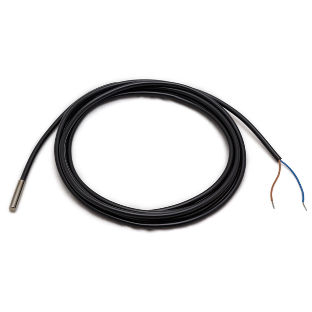
A heat sensor is an electronic device designed to detect and measure temperature within a specified range. It is a critical component in systems where temperature regulation is essential, such as in climate control systems, industrial processes, and consumer electronics. Heat sensors come in various forms, including thermistors, thermocouples, and infrared sensors, each with its unique characteristics and applications.
Explore Projects Built with heat sesor
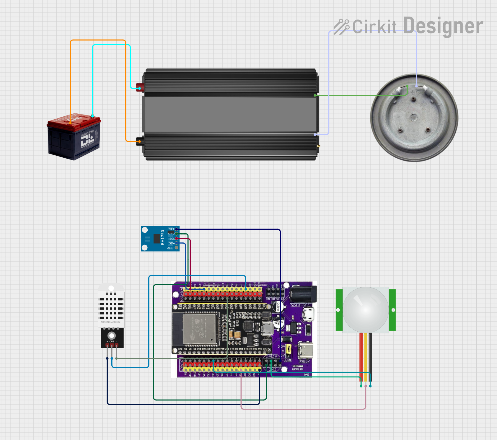
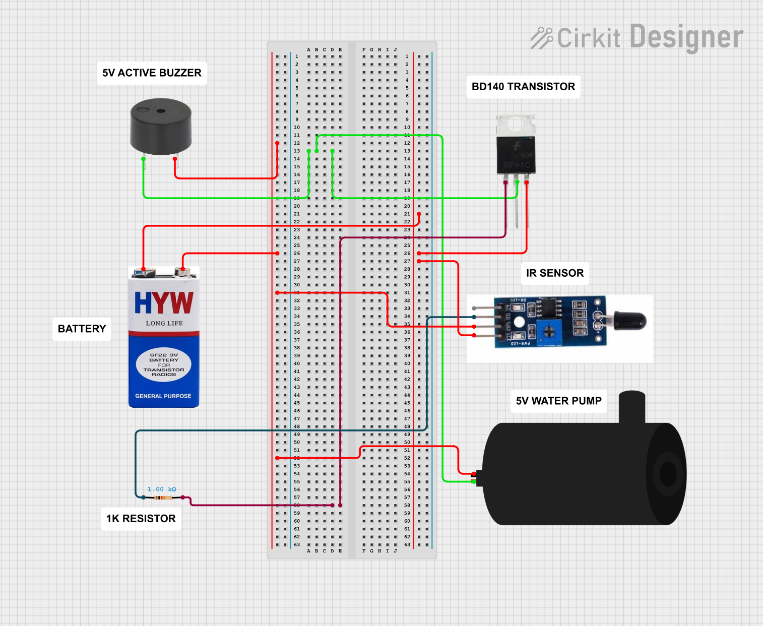
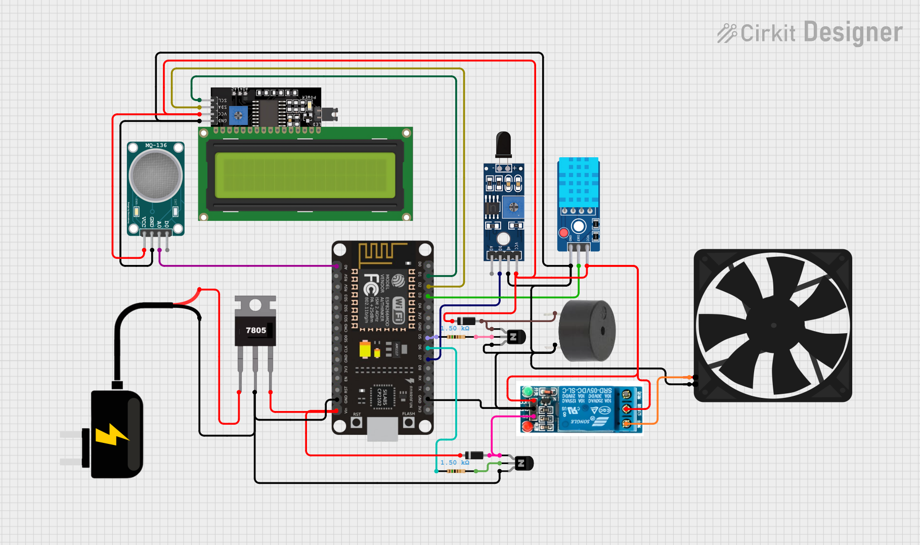
Explore Projects Built with heat sesor
Common Applications and Use Cases
- Climate Control: Used in HVAC systems to maintain desired room temperatures.
- Industrial Monitoring: Monitors temperatures in manufacturing processes.
- Consumer Electronics: Ensures safe operation of devices by monitoring heat.
- Automotive: Monitors engine and cabin temperatures.
- Safety Systems: Detects overheating to prevent fires in electrical systems.
Technical Specifications
Key Technical Details
- Temperature Range: -55°C to +150°C (varies by sensor type)
- Accuracy: ±0.5°C (typical for digital sensors)
- Output: Analog or Digital (depending on the sensor type)
- Supply Voltage: 3.3V to 5V (typical for most sensors)
- Current Consumption: 0.5mA to 10mA (varies by sensor type)
Pin Configuration and Descriptions
| Pin Number | Description | Notes |
|---|---|---|
| 1 | VCC (Power Supply) | Connect to 3.3V or 5V |
| 2 | Output (Analog/Digital) | Analog voltage or digital signal |
| 3 | Ground (GND) | Connect to system ground |
Note: The actual pin configuration may vary depending on the specific heat sensor model.
Usage Instructions
How to Use the Component in a Circuit
- Power Supply: Connect the VCC pin to a suitable power source (3.3V or 5V).
- Signal Output: Connect the output pin to an analog input if it's an analog sensor, or to a digital input if it's a digital sensor.
- Ground Connection: Connect the GND pin to the ground of the circuit.
Important Considerations and Best Practices
- Ensure the sensor is within the specified temperature range for accurate readings.
- Avoid placing the sensor near heat-generating components to prevent false readings.
- Use appropriate filtering or shielding to minimize noise in the signal.
- Follow the manufacturer's guidelines for calibration and environmental considerations.
Example Code for Arduino UNO
// Example code for interfacing a heat sensor with an Arduino UNO

const int heatSensorPin = A0; // Analog input pin connected to the heat sensor

void setup() {
  Serial.begin(9600); // Initialize serial communication at 9600 baud rate
}

void loop() {
  int sensorValue = analogRead(heatSensorPin); // Read the sensor value
  float temperature = convertToTemperature(sensorValue); // Convert to temperature
  Serial.print("Temperature: ");
  Serial.print(temperature);
  Serial.println(" C");
  delay(1000); // Wait for 1 second before reading again
}

// Function to convert the analog reading to temperature
float convertToTemperature(int sensorValue) {
  // Conversion logic depends on the specific heat sensor used
  // This is a placeholder for the actual conversion code
  float voltage = sensorValue * (5.0 / 1023.0); // Convert to voltage
  float temperature = (voltage - 0.5) * 100; // Convert voltage to temperature
  return temperature;
}
Note: The conversion function convertToTemperature is a placeholder and should be replaced with the actual conversion logic based on the specific heat sensor's datasheet.
Troubleshooting and FAQs
Common Issues Users Might Face
- Inaccurate Readings: Ensure the sensor is not subjected to sudden temperature changes or placed near heat sources.
- No Output Signal: Check the power supply and wiring connections to the sensor.
- Erratic Readings: Use shielded cables and proper grounding to minimize electrical noise.
Solutions and Tips for Troubleshooting
- Calibration: Periodically calibrate the sensor as per the manufacturer's instructions.
- Environmental Factors: Consider the ambient conditions that might affect the sensor's performance.
- Sensor Placement: Install the sensor away from direct sunlight or other heat sources for accurate measurements.
FAQs
Q: Can I use the heat sensor with both 3.3V and 5V systems? A: Yes, most heat sensors can operate within a range of 3.3V to 5V. Check the datasheet for your specific model.
Q: How do I calibrate my heat sensor? A: Calibration procedures vary by sensor type. Refer to the manufacturer's documentation for instructions.
Q: What is the difference between a thermistor and a thermocouple? A: A thermistor is a resistor whose resistance changes with temperature, while a thermocouple generates a voltage proportional to the temperature difference between two junctions.
Q: How long do heat sensors typically last? A: The lifespan of a heat sensor depends on its usage and environmental conditions. Generally, they are designed for long-term reliability.
Note: This documentation is a general guide and may not apply to all heat sensors. Always refer to the specific datasheet provided by the manufacturer for detailed information.