
How to Use Hi-Link 5V/2A: Examples, Pinouts, and Specs
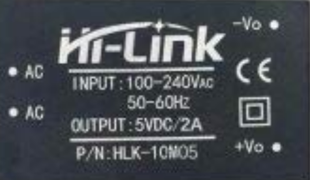
 Design with Hi-Link 5V/2A in Cirkit Designer
Introduction
The Hi-Link HLK-10M05 is a compact and efficient DC-DC converter module designed to provide a stable 5V output with a maximum current of 2A. This module is ideal for powering a wide range of electronic devices, including microcontrollers, sensors, and other low-power components. Its small size and high efficiency make it a popular choice for embedded systems, IoT devices, and portable electronics.
Explore Projects Built with Hi-Link 5V/2A
 Open Project in Cirkit Designer
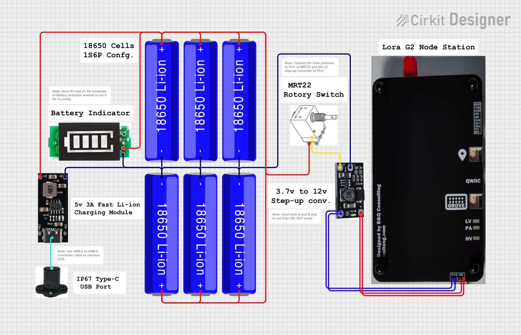 Open Project in Cirkit Designer
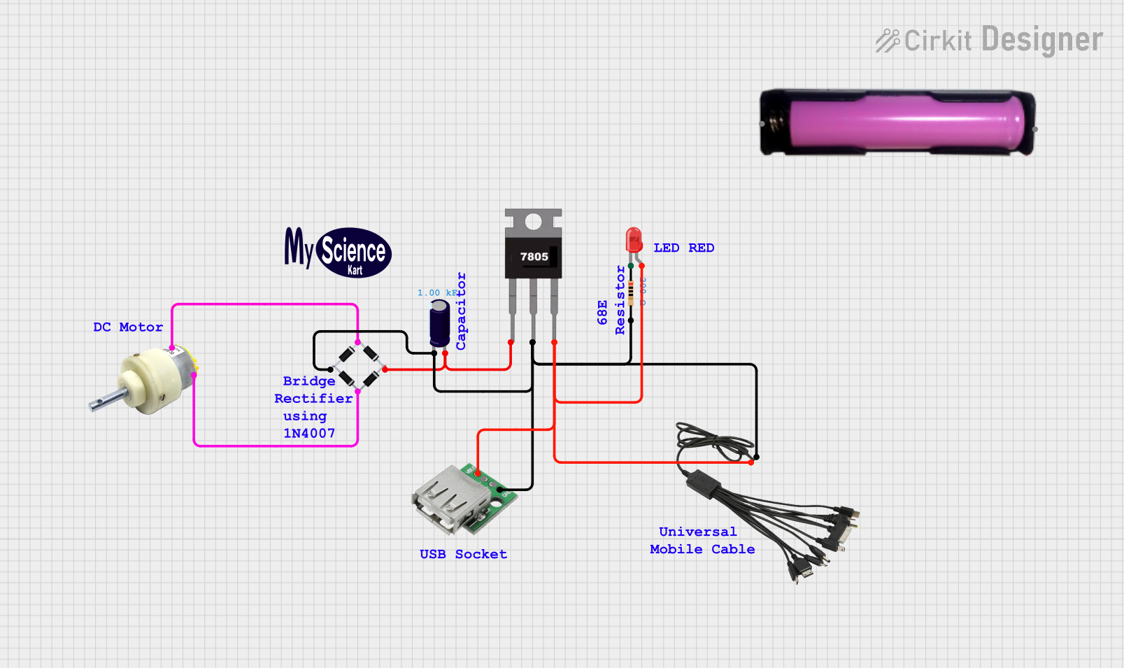 Open Project in Cirkit Designer
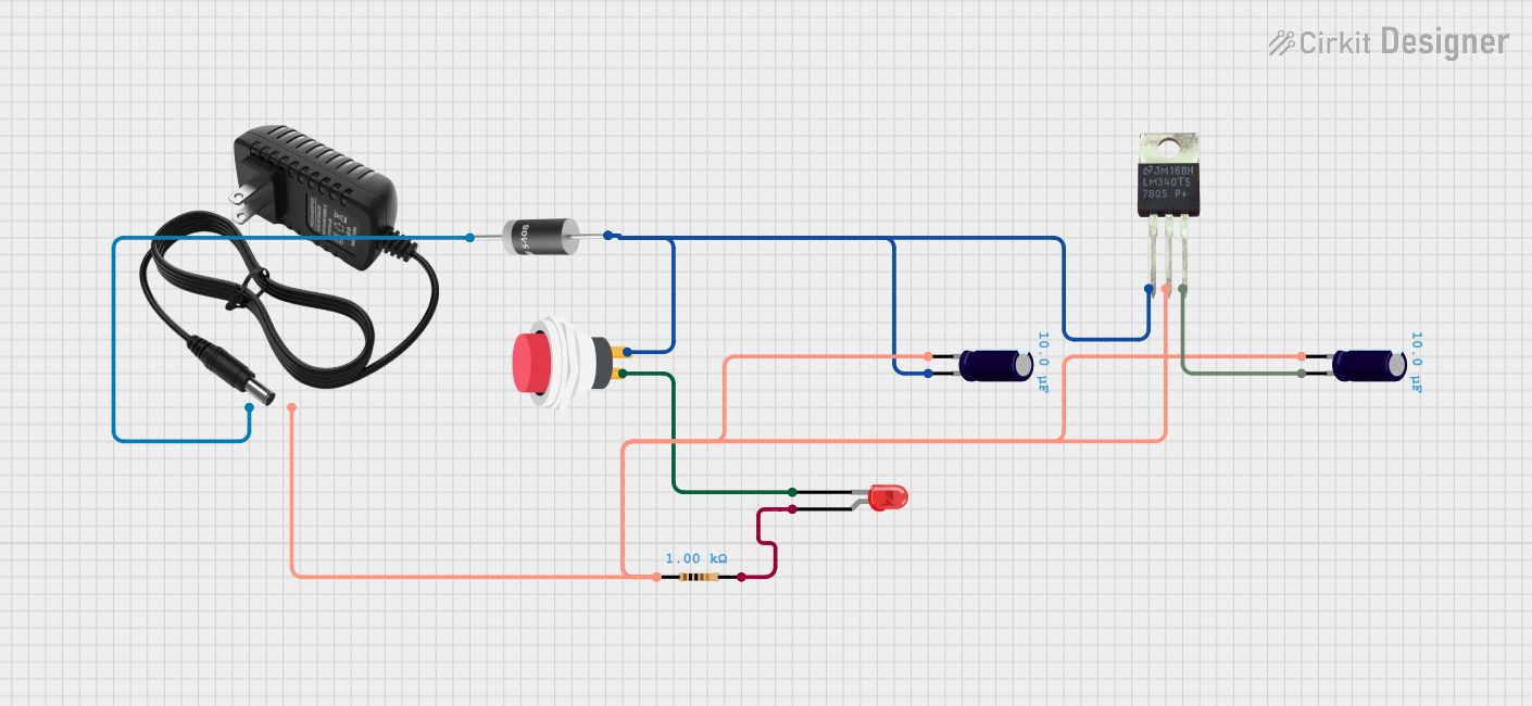 Open Project in Cirkit Designer
Explore Projects Built with Hi-Link 5V/2A
Open Project in Cirkit DesignerOpen Project in Cirkit DesignerOpen Project in Cirkit DesignerOpen Project in Cirkit DesignerCommon Applications
- Powering microcontrollers (e.g., Arduino, ESP32, Raspberry Pi Pico)
- Supplying power to sensors and actuators in IoT projects
- Replacing bulky linear voltage regulators in compact designs
- Battery-powered devices requiring efficient voltage conversion
- General-purpose 5V power supply for electronic circuits
Technical Specifications
The following table outlines the key technical details of the HLK-10M05 module:
| Parameter | Value |
|---|---|
| Input Voltage Range | 8V to 36V DC |
| Output Voltage | 5V DC |
| Maximum Output Current | 2A |
| Output Power | 10W |
| Efficiency | Up to 92% |
| Operating Temperature | -40°C to +85°C |
| Dimensions | 48mm x 25mm x 15mm |
| Weight | ~20g |
| Protection Features | Overcurrent, Overvoltage, Short Circuit |
Pin Configuration
The HLK-10M05 module has four pins for input and output connections. The pin configuration is as follows:
| Pin | Name | Description |
|---|---|---|
| 1 | VIN+ | Positive input voltage (8V to 36V) |
| 2 | VIN- | Negative input voltage (GND) |
| 3 | VOUT+ | Positive 5V output |
| 4 | VOUT- | Negative 5V output (GND) |
Usage Instructions
How to Use the HLK-10M05 in a Circuit
- Input Voltage Connection: Connect the VIN+ pin to the positive terminal of your DC power source (8V to 36V) and the VIN- pin to the ground (GND) of the power source.
- Output Voltage Connection: Connect the VOUT+ pin to the positive terminal of your load (e.g., microcontroller, sensor) and the VOUT- pin to the ground (GND) of your load.
- Bypass Capacitors: For improved stability, place a 10µF electrolytic capacitor and a 0.1µF ceramic capacitor across the output terminals (VOUT+ and VOUT-).
- Heat Dissipation: Ensure adequate ventilation or attach a heatsink if the module operates near its maximum load (2A) for extended periods.
Important Considerations
- Input Voltage Range: Ensure the input voltage remains within the specified range (8V to 36V). Exceeding this range may damage the module.
- Load Requirements: Do not exceed the maximum output current of 2A to avoid triggering the overcurrent protection.
- Polarity: Double-check the polarity of the input and output connections to prevent damage.
- Mounting: Secure the module in your circuit using screws or adhesive to prevent movement during operation.
Example: Using HLK-10M05 with Arduino UNO
The HLK-10M05 can be used to power an Arduino UNO from a 12V DC power source. Below is an example circuit and Arduino code to blink an LED:
Circuit Connections
- Connect the 12V DC power source to VIN+ and VIN- of the HLK-10M05.
- Connect VOUT+ to the Arduino UNO's 5V pin and VOUT- to the GND pin.
- Connect an LED with a 220Ω resistor to pin 13 of the Arduino UNO.
Arduino Code
// Simple LED Blink Example
// This code blinks an LED connected to pin 13 of the Arduino UNO.

void setup() {
  pinMode(13, OUTPUT); // Set pin 13 as an output pin
}

void loop() {
  digitalWrite(13, HIGH); // Turn the LED on
  delay(1000);            // Wait for 1 second
  digitalWrite(13, LOW);  // Turn the LED off
  delay(1000);            // Wait for 1 second
}
Troubleshooting and FAQs
Common Issues and Solutions
No Output Voltage
- Cause: Incorrect input voltage or loose connections.
- Solution: Verify that the input voltage is within the 8V to 36V range and check all connections.
Overheating
- Cause: Operating near the maximum load (2A) without proper ventilation.
- Solution: Add a heatsink or improve airflow around the module.
Output Voltage Fluctuations
- Cause: Insufficient bypass capacitors or unstable input voltage.
- Solution: Add a 10µF electrolytic capacitor and a 0.1µF ceramic capacitor across the output terminals.
Module Not Powering the Load
- Cause: Load exceeds the maximum output current (2A).
- Solution: Reduce the load current or use a higher-capacity power supply.
FAQs
Q1: Can the HLK-10M05 be used with a battery as the input source?
A1: Yes, the module can be powered by a battery as long as the battery voltage is within the 8V to 36V range.
Q2: Is the HLK-10M05 suitable for powering a Raspberry Pi?
A2: The HLK-10M05 can power a Raspberry Pi Zero or similar low-power models. However, it may not be sufficient for higher-power models like the Raspberry Pi 4, especially when peripherals are connected.
Q3: Does the module require additional cooling?
A3: Cooling is not required for light loads. For continuous operation near the maximum load (2A), a heatsink or proper ventilation is recommended.
Q4: Can I use the HLK-10M05 in outdoor applications?
A4: The module is not waterproof. If used outdoors, it must be enclosed in a weatherproof housing.