
How to Use LM5007: Examples, Pinouts, and Specs
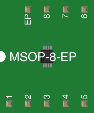
 Design with LM5007 in Cirkit Designer
Introduction
The LM5007, manufactured by Texas Instruments, is a high-voltage, step-down (buck) switching regulator designed for applications requiring high efficiency and low power consumption. It operates over a wide input voltage range (up to 75V) and provides an adjustable output voltage, making it suitable for a variety of power supply designs. The LM5007 integrates key features such as thermal shutdown, current limiting, and an internal high-voltage power MOSFET, simplifying the design process for engineers.
Explore Projects Built with LM5007
 Open Project in Cirkit Designer
 Open Project in Cirkit Designer
 Open Project in Cirkit Designer
 Open Project in Cirkit Designer
Explore Projects Built with LM5007
Open Project in Cirkit DesignerOpen Project in Cirkit DesignerOpen Project in Cirkit DesignerOpen Project in Cirkit DesignerCommon Applications
- Industrial power supplies
- Battery-powered systems
- Distributed power systems
- Automotive electronics
- LED drivers
Technical Specifications
Key Technical Details
| Parameter | Value |
|---|---|
| Input Voltage Range | 9V to 75V |
| Output Voltage Range | Adjustable (1.225V to 70V) |
| Output Current | Up to 0.5A |
| Switching Frequency | 600 kHz (nominal) |
| Efficiency | Up to 90% (depending on load and design) |
| Operating Temperature Range | -40°C to +125°C |
| Package Options | SOIC-8 (D) |
Pin Configuration and Descriptions
The LM5007 is available in an 8-pin SOIC package. Below is the pinout and description:
| Pin No. | Pin Name | Description |
|---|---|---|
| 1 | SW | Switch node. Connect to the inductor and freewheeling diode. |
| 2 | BST | Bootstrap capacitor connection. Connect a capacitor between BST and SW. |
| 3 | RCL | Current limit resistor. Sets the peak current limit of the internal switch. |
| 4 | RT | Timing resistor. Sets the switching frequency. |
| 5 | FB | Feedback input. Connect to a resistor divider to set the output voltage. |
| 6 | GND | Ground. Connect to system ground. |
| 7 | VIN | Input voltage. Connect to the power supply input. |
| 8 | VCC | Internal regulator output. Connect a capacitor to ground. |
Usage Instructions
How to Use the LM5007 in a Circuit
- Input Voltage Supply: Ensure the input voltage is within the range of 9V to 75V. Use a decoupling capacitor (e.g., 10 µF) close to the VIN pin to reduce noise.
- Output Voltage Adjustment: Use a resistor divider network connected to the FB pin to set the desired output voltage. The formula for output voltage is: [ V_{OUT} = V_{REF} \times \left(1 + \frac{R_1}{R_2}\right) ] where ( V_{REF} ) is 1.225V.
- Switching Frequency: Select a resistor value for the RT pin to set the switching frequency. Refer to the datasheet for the resistor value corresponding to your desired frequency.
- Bootstrap Capacitor: Connect a 0.01 µF to 0.1 µF capacitor between the BST and SW pins.
- Inductor Selection: Choose an inductor with a current rating higher than the peak output current and an inductance value that ensures stable operation.
- Diode Selection: Use a Schottky diode with a reverse voltage rating higher than the input voltage and a current rating higher than the output current.
- Thermal Management: Ensure adequate heat dissipation by using a proper PCB layout with thermal vias and copper planes.
Example Circuit with Arduino UNO
The LM5007 can be used to power an Arduino UNO by stepping down a higher voltage (e.g., 24V) to 5V. Below is an example circuit configuration:
- Input Voltage: 24V
- Output Voltage: 5V
- Output Current: 0.5A
// Example Arduino code to test the LM5007 output
// This code reads the 5V output from the LM5007 and blinks an LED if the voltage is stable.

const int voltagePin = A0; // Analog pin to read the output voltage
const int ledPin = 13;     // Onboard LED pin

void setup() {
  pinMode(ledPin, OUTPUT);
  Serial.begin(9600); // Initialize serial communication
}

void loop() {
  int sensorValue = analogRead(voltagePin); // Read the voltage
  float voltage = sensorValue * (5.0 / 1023.0); // Convert to actual voltage

  Serial.print("Voltage: ");
  Serial.println(voltage); // Print the voltage to the Serial Monitor

  if (voltage > 4.8 && voltage < 5.2) {
    digitalWrite(ledPin, HIGH); // Turn on LED if voltage is stable
  } else {
    digitalWrite(ledPin, LOW);  // Turn off LED if voltage is out of range
  }

  delay(1000); // Wait for 1 second
}
Important Considerations
- Use low-ESR capacitors for input and output filtering to minimize ripple.
- Ensure the feedback resistor divider is placed close to the FB pin to reduce noise.
- Avoid exceeding the maximum input voltage (75V) to prevent damage to the device.
- Follow the recommended PCB layout guidelines in the datasheet for optimal performance.
Troubleshooting and FAQs
Common Issues and Solutions
Output Voltage is Incorrect
- Verify the resistor divider values connected to the FB pin.
- Check for loose or incorrect connections in the circuit.
Excessive Heat Generation
- Ensure proper thermal management with adequate copper area for heat dissipation.
- Verify that the input voltage and load current are within the specified range.
Switching Noise or Instability
- Use low-ESR capacitors for input and output filtering.
- Ensure the bootstrap capacitor is properly connected between BST and SW pins.
No Output Voltage
- Check the input voltage to ensure it is within the specified range.
- Verify that the inductor and diode are correctly rated and connected.
FAQs
Q: Can the LM5007 be used for 12V to 5V conversion?
A: Yes, the LM5007 is suitable for stepping down 12V to 5V. Ensure proper component selection for stable operation.
Q: What is the maximum output current of the LM5007?
A: The LM5007 can provide up to 0.5A of output current.
Q: Can I use the LM5007 for battery-powered applications?
A: Yes, the LM5007 is ideal for battery-powered systems due to its high efficiency and wide input voltage range.
Q: How do I calculate the inductor value?
A: Refer to the datasheet for detailed guidelines on selecting the inductor value based on your input voltage, output voltage, and load current.
By following this documentation, users can effectively integrate the LM5007 into their designs for reliable and efficient power regulation.