How to Use Tilt Sensoe: Examples, Pinouts, and Specs
Introduction
A tilt sensor detects the orientation or inclination of an object relative to gravity. It is a simple yet effective component used to determine position or movement. Tilt sensors are commonly found in applications such as mobile devices, robotics, gaming controllers, and industrial equipment. They are ideal for detecting angular changes or triggering actions based on the tilt of an object.
Explore Projects Built with Tilt Sensoe
Explore Projects Built with Tilt Sensoe
Technical Specifications
- Type: Mechanical or MEMS-based tilt sensor
- Operating Voltage: 3.3V to 5V
- Current Consumption: Typically < 10mA
- Output Type: Digital (High/Low)
- Response Time: < 1ms
- Operating Temperature: -10°C to 70°C
- Durability: Up to 100,000 tilt cycles (varies by model)
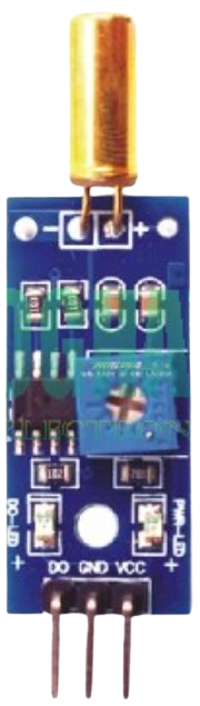
Pin Configuration and Descriptions
| Pin | Name | Description |
|---|---|---|
| 1 | VCC | Power supply pin. Connect to 3.3V or 5V. |
| 2 | GND | Ground pin. Connect to the ground of the circuit. |
| 3 | Signal | Digital output pin. Outputs HIGH when the sensor is upright, LOW when tilted. |
Usage Instructions
How to Use the Tilt Sensor in a Circuit
- Power the Sensor: Connect the VCC pin to a 3.3V or 5V power source and the GND pin to the ground.
- Connect the Signal Pin: Attach the Signal pin to a digital input pin on your microcontroller or microprocessor.
- Read the Output: The Signal pin outputs a HIGH (logic 1) when the sensor is upright and a LOW (logic 0) when tilted.
- Add a Pull-Down Resistor: To ensure stable readings, connect a 10kΩ pull-down resistor between the Signal pin and GND.
Important Considerations and Best Practices
- Debouncing: Mechanical tilt sensors may produce noisy signals due to contact bouncing. Use software debouncing or a capacitor (e.g., 0.1µF) across the Signal pin and GND to filter out noise.
- Orientation: Ensure the sensor is mounted in the correct orientation for your application.
- Avoid Excessive Vibration: Prolonged vibration can reduce the lifespan of mechanical tilt sensors.
- Voltage Compatibility: Verify that the sensor's operating voltage matches your circuit's power supply.
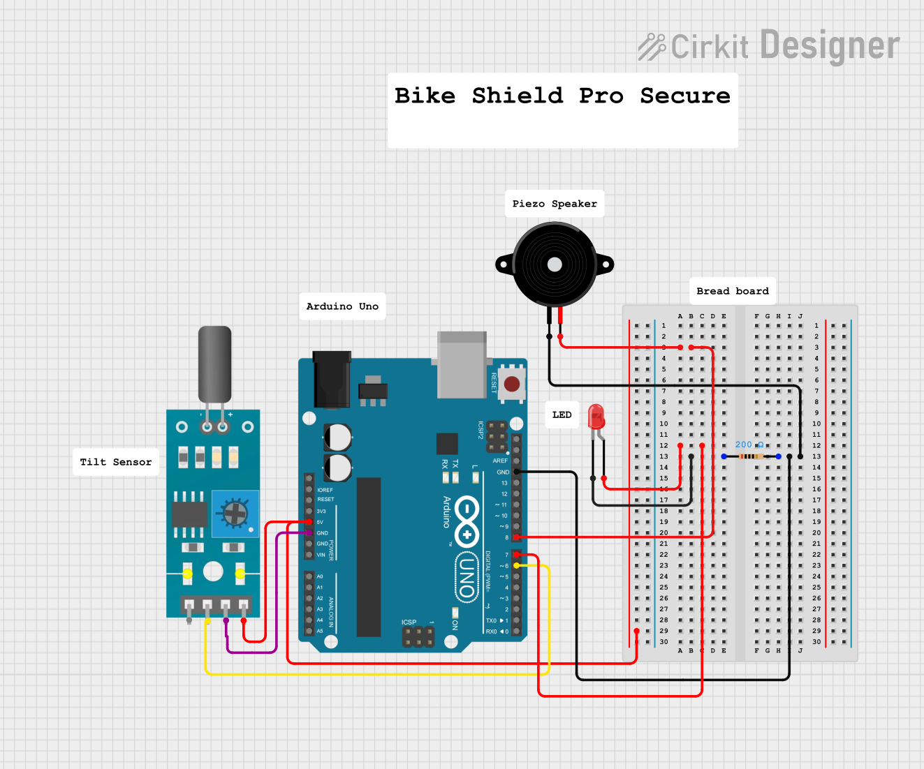
Example: Using a Tilt Sensor with Arduino UNO
Below is an example of how to connect and use a tilt sensor with an Arduino UNO:
Circuit Connections
- VCC: Connect to Arduino 5V pin.
- GND: Connect to Arduino GND pin.
- Signal: Connect to Arduino digital pin 2.
Arduino Code
// Define the pin connected to the tilt sensor's Signal pin
const int tiltSensorPin = 2;

// Define an LED pin for visual feedback
const int ledPin = 13;

void setup() {
  // Initialize the tilt sensor pin as an input
  pinMode(tiltSensorPin, INPUT);

  // Initialize the LED pin as an output
  pinMode(ledPin, OUTPUT);

  // Start the serial communication for debugging
  Serial.begin(9600);
}

void loop() {
  // Read the state of the tilt sensor
  int tiltState = digitalRead(tiltSensorPin);

  // Print the tilt state to the Serial Monitor
  Serial.print("Tilt Sensor State: ");
  Serial.println(tiltState);

  // If the sensor is upright (HIGH), turn on the LED
  if (tiltState == HIGH) {
    digitalWrite(ledPin, HIGH);
  } else {
    // If the sensor is tilted (LOW), turn off the LED
    digitalWrite(ledPin, LOW);
  }

  // Add a small delay to stabilize readings
  delay(100);
}
Troubleshooting and FAQs
Common Issues and Solutions
No Output Signal:
- Cause: Incorrect wiring or loose connections.
- Solution: Double-check all connections, especially the VCC, GND, and Signal pins.
Unstable or Noisy Readings:
- Cause: Contact bouncing in mechanical sensors.
- Solution: Add a 0.1µF capacitor across the Signal pin and GND or implement software debouncing.
Sensor Not Responding to Tilt:
- Cause: Incorrect orientation or damaged sensor.
- Solution: Verify the sensor's orientation and replace it if necessary.
Output Always HIGH or LOW:
- Cause: Missing pull-down resistor or faulty sensor.
- Solution: Add a 10kΩ pull-down resistor and test the sensor with a multimeter.
FAQs
Q1: Can I use the tilt sensor with a 3.3V microcontroller?
A1: Yes, most tilt sensors operate within a voltage range of 3.3V to 5V. Ensure your sensor is compatible with 3.3V logic levels.
Q2: How do I debounce the tilt sensor in software?
A2: You can use a simple delay or implement a debounce algorithm in your code to filter out rapid signal changes.
Q3: Can the tilt sensor detect precise angles?
A3: No, tilt sensors are binary devices that only detect upright or tilted states. For precise angle measurements, use an accelerometer or gyroscope.
Q4: Is the tilt sensor waterproof?
A4: Most tilt sensors are not waterproof. If you need to use the sensor in a wet environment, consider sealing it in a waterproof enclosure.