Cirkit Designer Logo
Cirkit Designer
Your all-in-one circuit design IDE
Home / 
Component Documentation

How to Use C Step-Down Module: Examples, Pinouts, and Specs

Image of C Step-Down Module
Cirkit Designer LogoDesign with C Step-Down Module in Cirkit Designer

Introduction

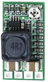
The C Step-Down Module, commonly referred to as a buck converter, is an essential component in power management and regulation. It efficiently converts a higher input voltage to a lower output voltage, maintaining a stable and regulated output for a variety of electronic devices. This module is widely used in battery-operated devices, embedded systems, and any application where voltage regulation is critical to protect sensitive electronics.

Explore Projects Built with C Step-Down Module

Use Cirkit Designer to design, explore, and prototype these projects online. Some projects support real-time simulation. Click "Open Project" to start designing instantly!
Battery-Powered UPS with Step-Down Buck Converter and BMS
Image of Mini ups: A project utilizing C Step-Down Module in a practical application
This circuit is a power management system that steps down a 240V AC input to a lower DC voltage using a buck converter, which then powers a 40W UPS. The UPS is controlled by a rocker switch and is backed up by a battery management system (BMS) connected to three 3.7V batteries in series, ensuring continuous power supply.
Cirkit Designer LogoOpen Project in Cirkit Designer
Voltage Regulation System with MT3608 Boost and LM2596 Buck Converters
Image of solar system router ups: A project utilizing C Step-Down Module in a practical application
This circuit consists of two MT3608 boost converters and an LM2596 step-down module, each connected to separate 12V power supplies. The MT3608 modules are configured to step up the voltage from their respective power supplies, while the LM2596 module steps down the voltage from a 12V battery. Diodes are used to ensure correct current flow direction, potentially for protection or isolation between different parts of the circuit.
Cirkit Designer LogoOpen Project in Cirkit Designer
DC-DC Converter and Relay Module Power Distribution System
Image of relay: A project utilizing C Step-Down Module in a practical application
This circuit consists of a DC-DC converter powering a 6-channel power module, which in turn supplies 5V to a 2-relay module. The power module distributes the converted voltage to the relay module, enabling it to control external devices.
Cirkit Designer LogoOpen Project in Cirkit Designer
ESP32-Based Smart Energy Monitoring and Control System
Image of SMART SOCKET: A project utilizing C Step-Down Module in a practical application
This circuit is designed to monitor AC voltage and current using ZMPT101B and ZMCT103C sensors, respectively, with an ESP32 microcontroller processing the sensor outputs. The XL4015 step-down module regulates the power supply to provide a stable voltage to the sensors, the ESP32, and an LCD I2C display. The ESP32 controls a 4-channel relay module for switching AC loads, and the system's operation can be interacted with via the LCD display and a push switch.
Cirkit Designer LogoOpen Project in Cirkit Designer

Explore Projects Built with C Step-Down Module

Use Cirkit Designer to design, explore, and prototype these projects online. Some projects support real-time simulation. Click "Open Project" to start designing instantly!
Image of Mini ups: A project utilizing C Step-Down Module in a practical application
Battery-Powered UPS with Step-Down Buck Converter and BMS
This circuit is a power management system that steps down a 240V AC input to a lower DC voltage using a buck converter, which then powers a 40W UPS. The UPS is controlled by a rocker switch and is backed up by a battery management system (BMS) connected to three 3.7V batteries in series, ensuring continuous power supply.
Cirkit Designer LogoOpen Project in Cirkit Designer
Image of solar system router ups: A project utilizing C Step-Down Module in a practical application
Voltage Regulation System with MT3608 Boost and LM2596 Buck Converters
This circuit consists of two MT3608 boost converters and an LM2596 step-down module, each connected to separate 12V power supplies. The MT3608 modules are configured to step up the voltage from their respective power supplies, while the LM2596 module steps down the voltage from a 12V battery. Diodes are used to ensure correct current flow direction, potentially for protection or isolation between different parts of the circuit.
Cirkit Designer LogoOpen Project in Cirkit Designer
Image of relay: A project utilizing C Step-Down Module in a practical application
DC-DC Converter and Relay Module Power Distribution System
This circuit consists of a DC-DC converter powering a 6-channel power module, which in turn supplies 5V to a 2-relay module. The power module distributes the converted voltage to the relay module, enabling it to control external devices.
Cirkit Designer LogoOpen Project in Cirkit Designer
Image of SMART SOCKET: A project utilizing C Step-Down Module in a practical application
ESP32-Based Smart Energy Monitoring and Control System
This circuit is designed to monitor AC voltage and current using ZMPT101B and ZMCT103C sensors, respectively, with an ESP32 microcontroller processing the sensor outputs. The XL4015 step-down module regulates the power supply to provide a stable voltage to the sensors, the ESP32, and an LCD I2C display. The ESP32 controls a 4-channel relay module for switching AC loads, and the system's operation can be interacted with via the LCD display and a push switch.
Cirkit Designer LogoOpen Project in Cirkit Designer

Common Applications and Use Cases

  • Power supply for embedded systems
  • Voltage regulation for battery-operated devices
  • Automotive electronics to step down battery voltage
  • Renewable energy systems, such as solar power converters
  • LED drivers for lighting systems

Technical Specifications

Key Technical Details

Parameter Value Description
Input Voltage XX V to XX V The voltage range the module can accept.
Output Voltage XX V to XX V The regulated voltage the module provides.
Maximum Output Current XX A The maximum current the module can supply.
Efficiency XX% Typical efficiency at full load.
Switching Frequency XX kHz Frequency at which the module switches.
Operating Temperature XX°C to XX°C Safe ambient temperature range.

Pin Configuration and Descriptions

Pin Number Name Description
1 VIN Input voltage. Connect to the positive voltage supply.
2 GND Ground. Connect to the system ground.
3 VOUT Regulated output voltage. Connect to the load.
4 ADJ Adjustment pin. Used to set the output voltage.
5 EN Enable pin. Logic high enables the module.

Usage Instructions

How to Use the Component in a Circuit

  1. Connect the positive terminal of your voltage source to the VIN pin of the module.
  2. Connect the ground terminal of your voltage source to the GND pin.
  3. Set the desired output voltage by adjusting the potentiometer connected to the ADJ pin, if applicable.
  4. Connect the load to the VOUT pin.
  5. Apply a logic high signal to the EN pin to enable the module.

Important Considerations and Best Practices

  • Ensure that the input voltage does not exceed the maximum rating of the module.
  • Do not exceed the maximum output current to prevent overheating and potential damage.
  • Use proper heat sinking if operating near the maximum output current.
  • Keep the switching frequency in mind when designing the circuit to avoid interference with other components.
  • Place capacitors close to the input and output pins for better filtering and stability.

Troubleshooting and FAQs

Common Issues Users Might Face

  • Output voltage is too high or too low: Check the ADJ pin setting and ensure it is properly adjusted.
  • Module is not powering on: Verify that the EN pin is receiving a logic high signal.
  • Module is overheating: Ensure the current draw is within the module's limits and improve heat dissipation.

Solutions and Tips for Troubleshooting

  • If the output voltage is incorrect, recalibrate the potentiometer connected to the ADJ pin.
  • Confirm that all connections are secure and there are no loose wires or cold solder joints.
  • If the module is not responding, check the input voltage and the EN pin voltage.
  • For overheating issues, reduce the load current or enhance cooling with a heatsink or fan.

FAQs

Q: Can I use the C Step-Down Module to charge batteries? A: Yes, but ensure the output voltage is appropriate for the battery and include proper charging circuitry.

Q: What should I do if the output voltage fluctuates? A: Fluctuations can be due to load variations or insufficient filtering. Add capacitors to the input and output for stability.

Q: Is it possible to synchronize the switching frequency with other devices? A: This depends on the specific module. Some step-down modules offer a synchronization input for this purpose.

Example Code for Arduino UNO

// Example code to control the C Step-Down Module with an Arduino UNO

const int enablePin = 3; // Connect to the EN pin of the module

void setup() {
  pinMode(enablePin, OUTPUT);
  digitalWrite(enablePin, LOW); // Start with the module disabled
}

void loop() {
  // Enable the module
  digitalWrite(enablePin, HIGH);
  delay(5000); // Keep the module enabled for 5 seconds

  // Disable the module
  digitalWrite(enablePin, LOW);
  delay(5000); // Keep the module disabled for 5 seconds
}

Note: This code is a simple example of how to enable and disable the C Step-Down Module using an Arduino UNO. Adjust the code to suit the specific requirements of your application.