Cirkit Designer Logo
Cirkit Designer
Your all-in-one circuit design IDE
Home / 
Component Documentation

How to Use PMS7003 : Examples, Pinouts, and Specs

Image of PMS7003
Cirkit Designer LogoDesign with PMS7003 in Cirkit Designer

Introduction

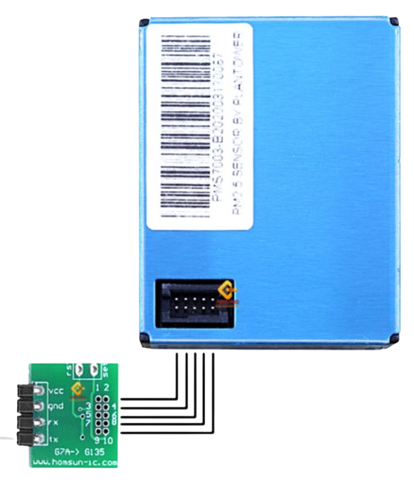
The PMS7003 is a digital particulate matter sensor designed to measure PM1.0, PM2.5, and PM10 concentrations in the air. It utilizes advanced laser scattering technology to detect and quantify airborne particles with high precision. The sensor outputs real-time data via a UART (serial) interface, making it easy to integrate into various systems. Its compact size, low power consumption, and reliable performance make it ideal for air quality monitoring applications.

Explore Projects Built with PMS7003

Use Cirkit Designer to design, explore, and prototype these projects online. Some projects support real-time simulation. Click "Open Project" to start designing instantly!
Cellular-Enabled IoT Device with Real-Time Clock and Power Management
Image of LRCM PHASE 2 BASIC: A project utilizing PMS7003  in a practical application
This circuit features a LilyGo-SIM7000G module for cellular communication and GPS functionality, interfaced with an RTC DS3231 for real-time clock capabilities. It includes voltage sensing through two voltage sensor modules, and uses an 8-channel opto-coupler for isolating different parts of the circuit. Power management is handled by a buck converter connected to a DC power source and batteries, with a fuse for protection and a rocker switch for on/off control. Additionally, there's an LED for indication purposes.
Cirkit Designer LogoOpen Project in Cirkit Designer
Arduino Mega 2560 Based Security System with Fingerprint Authentication and SMS Alerts
Image of Door security system: A project utilizing PMS7003  in a practical application
This circuit features an Arduino Mega 2560 microcontroller interfaced with a SIM800L GSM module, two fingerprint scanners, an I2C LCD display, an IR sensor, and a piezo buzzer. Power management is handled by a PowerBoost 1000 Basic Pad USB, a TP4056 charging module, and a Li-ion 18650 battery, with an option to use a Mini AC-DC 110V-230V to 5V 700mA module for direct power supply. The primary functionality appears to be a security system with GSM communication capabilities, biometric access control, and visual/audible feedback.
Cirkit Designer LogoOpen Project in Cirkit Designer
ESP32C3 and SIM800L Powered Smart Energy Monitor with OLED Display and Wi-Fi Connectivity
Image of SERVER: A project utilizing PMS7003  in a practical application
This circuit is a power monitoring system that uses an ESP32C3 microcontroller to collect power usage data from slave devices via WiFi and SMS. The collected data is displayed on a 0.96" OLED screen, and the system is powered by an AC-DC converter module. Additionally, the circuit includes a SIM800L GSM module for SMS communication and LEDs for status indication.
Cirkit Designer LogoOpen Project in Cirkit Designer
Battery-Powered Raspberry Pi Pico GPS Tracker with Sensor Integration
Image of Copy of CanSet v1: A project utilizing PMS7003  in a practical application
This circuit is a data acquisition and communication system powered by a LiPoly battery and managed by a Raspberry Pi Pico. It includes sensors (BMP280, MPU9250) for environmental data, a GPS module for location tracking, an SD card for data storage, and a WLR089-CanSAT for wireless communication. The TP4056 module handles battery charging, and a toggle switch controls power distribution.
Cirkit Designer LogoOpen Project in Cirkit Designer

Explore Projects Built with PMS7003

Use Cirkit Designer to design, explore, and prototype these projects online. Some projects support real-time simulation. Click "Open Project" to start designing instantly!
Image of LRCM PHASE 2 BASIC: A project utilizing PMS7003  in a practical application
Cellular-Enabled IoT Device with Real-Time Clock and Power Management
This circuit features a LilyGo-SIM7000G module for cellular communication and GPS functionality, interfaced with an RTC DS3231 for real-time clock capabilities. It includes voltage sensing through two voltage sensor modules, and uses an 8-channel opto-coupler for isolating different parts of the circuit. Power management is handled by a buck converter connected to a DC power source and batteries, with a fuse for protection and a rocker switch for on/off control. Additionally, there's an LED for indication purposes.
Cirkit Designer LogoOpen Project in Cirkit Designer
Image of Door security system: A project utilizing PMS7003  in a practical application
Arduino Mega 2560 Based Security System with Fingerprint Authentication and SMS Alerts
This circuit features an Arduino Mega 2560 microcontroller interfaced with a SIM800L GSM module, two fingerprint scanners, an I2C LCD display, an IR sensor, and a piezo buzzer. Power management is handled by a PowerBoost 1000 Basic Pad USB, a TP4056 charging module, and a Li-ion 18650 battery, with an option to use a Mini AC-DC 110V-230V to 5V 700mA module for direct power supply. The primary functionality appears to be a security system with GSM communication capabilities, biometric access control, and visual/audible feedback.
Cirkit Designer LogoOpen Project in Cirkit Designer
Image of SERVER: A project utilizing PMS7003  in a practical application
ESP32C3 and SIM800L Powered Smart Energy Monitor with OLED Display and Wi-Fi Connectivity
This circuit is a power monitoring system that uses an ESP32C3 microcontroller to collect power usage data from slave devices via WiFi and SMS. The collected data is displayed on a 0.96" OLED screen, and the system is powered by an AC-DC converter module. Additionally, the circuit includes a SIM800L GSM module for SMS communication and LEDs for status indication.
Cirkit Designer LogoOpen Project in Cirkit Designer
Image of Copy of CanSet v1: A project utilizing PMS7003  in a practical application
Battery-Powered Raspberry Pi Pico GPS Tracker with Sensor Integration
This circuit is a data acquisition and communication system powered by a LiPoly battery and managed by a Raspberry Pi Pico. It includes sensors (BMP280, MPU9250) for environmental data, a GPS module for location tracking, an SD card for data storage, and a WLR089-CanSAT for wireless communication. The TP4056 module handles battery charging, and a toggle switch controls power distribution.
Cirkit Designer LogoOpen Project in Cirkit Designer

Common Applications

  • Indoor and outdoor air quality monitoring
  • Smart home devices and IoT systems
  • HVAC (Heating, Ventilation, and Air Conditioning) systems
  • Environmental monitoring stations
  • Air purifiers and filtration systems

Technical Specifications

Below are the key technical details of the PMS7003 sensor:

Parameter Value
Measurement Range 0.3 µm to 10 µm (particle size)
PM Measurement Types PM1.0, PM2.5, PM10
Output Interface UART (3.3V logic level)
Operating Voltage 4.5V to 5.5V
Operating Current ≤ 100 mA
Standby Current ≤ 200 µA
Response Time ≤ 1 second
Operating Temperature -10°C to 60°C
Operating Humidity 0% to 99% RH (non-condensing)
Dimensions 50 mm × 38 mm × 21 mm
Weight ~50 g

Pin Configuration and Descriptions

The PMS7003 has a 7-pin connector for power, data communication, and control. Below is the pinout:

Pin Number Pin Name Description
1 VCC Power supply input (4.5V to 5.5V)
2 GND Ground
3 SET Sleep mode control (Low: Sleep, High: Active)
4 RX UART Receive (3.3V logic level)
5 TX UART Transmit (3.3V logic level)
6 RESET Reset pin (Low: Reset, High: Normal operation)
7 NC Not connected

Usage Instructions

How to Use the PMS7003 in a Circuit

  1. Power Supply: Connect the VCC pin to a 5V power source and the GND pin to ground.
  2. UART Communication: Connect the TX pin of the PMS7003 to the RX pin of your microcontroller, and the RX pin of the PMS7003 to the TX pin of your microcontroller. Ensure the microcontroller operates at 3.3V logic levels or use a level shifter if necessary.
  3. Sleep Mode Control: Use the SET pin to toggle between active and sleep modes. Pull the pin high for active mode and low for sleep mode.
  4. Reset: Optionally, connect the RESET pin to a GPIO pin on your microcontroller for manual resets.

Important Considerations

  • Airflow: Ensure the sensor is placed in an environment with proper airflow for accurate readings. Avoid obstructing the air inlet and outlet.
  • Orientation: Install the sensor in the recommended orientation (horizontal) for optimal performance.
  • Warm-Up Time: Allow the sensor to warm up for 30 seconds after powering on to stabilize readings.
  • UART Settings: Configure the UART interface with the following settings:
    • Baud Rate: 9600 bps
    • Data Bits: 8
    • Stop Bits: 1
    • Parity: None

Example Code for Arduino UNO

Below is an example of how to interface the PMS7003 with an Arduino UNO to read PM2.5 data:

#include <SoftwareSerial.h>

// Define the RX and TX pins for SoftwareSerial
SoftwareSerial pmsSerial(10, 11); // RX = Pin 10, TX = Pin 11

// Buffer to store incoming data from the PMS7003
uint8_t pmsData[32];

void setup() {
  Serial.begin(9600); // Initialize Serial Monitor
  pmsSerial.begin(9600); // Initialize PMS7003 UART communication

  Serial.println("PMS7003 Sensor Initialized");
}

void loop() {
  if (pmsSerial.available() >= 32) { // Check if 32 bytes are available
    for (int i = 0; i < 32; i++) {
      pmsData[i] = pmsSerial.read(); // Read data into buffer
    }

    // Verify the data frame header
    if (pmsData[0] == 0x42 && pmsData[1] == 0x4D) {
      // Extract PM2.5 concentration (bytes 12 and 13)
      uint16_t pm25 = (pmsData[12] << 8) | pmsData[13];

      // Print PM2.5 concentration to Serial Monitor
      Serial.print("PM2.5 Concentration: ");
      Serial.print(pm25);
      Serial.println(" µg/m³");
    }
  }

  delay(1000); // Wait 1 second before reading again
}

Notes:

  • Use a level shifter if connecting the PMS7003 to a 5V microcontroller like the Arduino UNO.
  • Ensure the sensor is not exposed to excessive dust or moisture, as this may affect its performance.

Troubleshooting and FAQs

Common Issues and Solutions

  1. No Data Output:

    • Ensure the sensor is powered correctly (4.5V to 5.5V).
    • Verify the UART connections (TX to RX and RX to TX).
    • Check the SET pin is pulled high for active mode.
  2. Incorrect Readings:

    • Allow the sensor to warm up for at least 30 seconds after powering on.
    • Ensure the sensor is installed in a clean, unobstructed environment with proper airflow.
  3. Frequent Resets:

    • Check the power supply for stability. Use a decoupling capacitor (e.g., 10 µF) near the VCC pin.
  4. Data Frame Errors:

    • Verify the UART settings (9600 bps, 8N1).
    • Ensure the data frame header (0x42, 0x4D) is received correctly.

FAQs

Q: Can the PMS7003 detect gases like CO2 or VOCs?
A: No, the PMS7003 is designed to measure particulate matter (PM1.0, PM2.5, PM10) and cannot detect gases.

Q: How often should the sensor be calibrated?
A: The PMS7003 is factory-calibrated and does not require user calibration. However, periodic cleaning of the air inlet/outlet may help maintain accuracy.

Q: Can the sensor operate continuously?
A: Yes, the PMS7003 is designed for continuous operation. However, using the sleep mode when not in use can extend its lifespan.

Q: Is the sensor affected by humidity?
A: The PMS7003 can operate in up to 99% relative humidity, but condensation should be avoided to prevent damage.