How to Use PCM5102A: Examples, Pinouts, and Specs
Introduction
The PCM5102A, manufactured by Texas Instruments, is a high-performance digital-to-analog converter (DAC) designed specifically for audio applications. It supports 32-bit audio processing and delivers exceptional audio quality with low distortion and a high signal-to-noise ratio (SNR). This makes it an ideal choice for high-fidelity audio systems, home theater setups, and professional audio equipment.
Explore Projects Built with PCM5102A


Explore Projects Built with PCM5102A
Common Applications
- High-fidelity audio systems
- Home theater receivers
- Digital audio players
- USB DACs for computers
- Professional audio equipment
- Wireless audio systems
Technical Specifications
Key Technical Details
- Audio Resolution: Up to 32-bit
- Sampling Rate: Supports up to 384 kHz
- Signal-to-Noise Ratio (SNR): 112 dB (typical)
- Total Harmonic Distortion + Noise (THD+N): -93 dB
- Output Voltage: 2.1 Vrms (typical)
- Power Supply Voltage:
- Analog: 3.3 V
- Digital: 1.8 V to 3.3 V
- Power Consumption: Low-power operation with typical consumption under 20 mW
- Interface: I²S (Inter-IC Sound) for digital audio input
- Package: 20-pin TSSOP (Thin Shrink Small Outline Package)
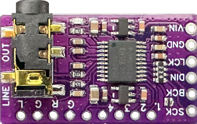
Pin Configuration and Descriptions
The PCM5102A comes in a 20-pin TSSOP package. Below is the pin configuration and description:
| Pin Number | Pin Name | Description |
|---|---|---|
| 1 | DVDD | Digital power supply (1.8 V to 3.3 V) |
| 2 | DGND | Digital ground |
| 3 | SCK | System clock input (optional for asynchronous mode) |
| 4 | BCK | Bit clock input for I²S interface |
| 5 | DIN | Digital audio data input (I²S format) |
| 6 | LRCK | Left-right clock input for I²S interface |
| 7 | FMT | Audio format selection (I²S, left-justified, or right-justified) |
| 8 | XSMT | Soft mute control (active low) |
| 9 | FLT | Filter selection (sharp or slow roll-off) |
| 10 | SCL | I²C clock input (optional, for advanced control) |
| 11 | SDA | I²C data input/output (optional, for advanced control) |
| 12 | NC | No connection |
| 13 | VCOM | Common-mode voltage output |
| 14 | AGND | Analog ground |
| 15 | VOUTL | Left-channel analog audio output |
| 16 | VOUTR | Right-channel analog audio output |
| 17 | AVDD | Analog power supply (3.3 V) |
| 18 | NC | No connection |
| 19 | NC | No connection |
| 20 | NC | No connection |
Usage Instructions
How to Use the PCM5102A in a Circuit
Power Supply:
- Connect the analog power supply (AVDD) to 3.3 V and the digital power supply (DVDD) to a voltage between 1.8 V and 3.3 V.
- Ensure proper decoupling capacitors are placed near the power supply pins to reduce noise.
I²S Interface:
- Connect the I²S signals (BCK, LRCK, and DIN) from your microcontroller, DSP, or audio source to the corresponding pins on the PCM5102A.
- If using an external system clock, connect it to the SCK pin. Otherwise, the PCM5102A can operate in asynchronous mode without an external clock.
Audio Output:
- Connect the left and right analog audio outputs (VOUTL and VOUTR) to your amplifier or audio output stage.
- Use proper filtering capacitors to ensure clean audio signals.
Control Pins:
- Use the FMT pin to select the desired audio format (I²S, left-justified, or right-justified).
- The FLT pin can be used to select between sharp and slow roll-off filters for audio processing.
- The XSMT pin can be used to enable or disable soft mute functionality.
PCB Layout:
- Keep the analog and digital ground planes separate to minimize noise.
- Place decoupling capacitors as close as possible to the power supply pins.
Example: Connecting PCM5102A to an Arduino UNO
The PCM5102A can be connected to an Arduino UNO using the I²S interface. Below is an example of how to configure the Arduino to send audio data to the PCM5102A.
Wiring Diagram
| PCM5102A Pin | Arduino Pin | Description |
|---|---|---|
| BCK | Pin 9 | Bit clock |
| LRCK | Pin 10 | Left-right clock |
| DIN | Pin 11 | Data input |
| DVDD | 3.3 V | Digital power supply |
| AVDD | 3.3 V | Analog power supply |
| DGND, AGND | GND | Ground |
Arduino Code
#include <I2S.h> // Include the I2S library for audio data transmission

void setup() {
  // Initialize the I2S interface in master mode
  if (!I2S.begin(I2S_PHILIPS_MODE, 44100, 32)) {
    // Check if I2S initialization failed
    while (1) {
      // Stay in an infinite loop if initialization fails
    }
  }
}

void loop() {
  // Generate a simple sine wave for testing
  for (int i = 0; i < 360; i++) {
    // Calculate the sine wave value
    int sample = (int)(sin(i * DEG_TO_RAD) * 32767);
    // Send the sample to the PCM5102A
    I2S.write(sample);
  }
}
Important Considerations
- Ensure the power supply voltages are within the specified range to avoid damaging the component.
- Use proper grounding techniques to minimize noise and interference.
- If using the I²C interface for advanced control, ensure pull-up resistors are connected to the SDA and SCL lines.
Troubleshooting and FAQs
Common Issues and Solutions
No Audio Output:
- Verify that the power supply voltages (AVDD and DVDD) are correct and stable.
- Check the I²S connections (BCK, LRCK, and DIN) for proper wiring.
- Ensure the audio source is configured to output data in a compatible format (e.g., I²S).
Distorted Audio:
- Check the decoupling capacitors near the power supply pins.
- Verify that the analog output stage is properly designed and free of noise.
High Noise or Interference:
- Ensure proper separation of analog and digital ground planes on the PCB.
- Use shielded cables for audio connections if necessary.
PCM5102A Overheating:
- Verify that the power supply voltages are within the specified range.
- Check for short circuits or excessive current draw in the circuit.
FAQs
Q: Can the PCM5102A operate without an external system clock?
A: Yes, the PCM5102A can operate in asynchronous mode without an external system clock. However, for best performance, an external clock is recommended.
Q: What audio formats does the PCM5102A support?
A: The PCM5102A supports I²S, left-justified, and right-justified audio formats.
Q: Can I use the PCM5102A with a 5 V microcontroller?
A: Yes, but you will need level shifters to convert the 5 V logic signals to 3.3 V for compatibility with the PCM5102A.
Q: How do I select the filter type?
A: Use the FLT pin to select between sharp and slow roll-off filters. Refer to the datasheet for more details on filter characteristics.