How to Use HDMI: Examples, Pinouts, and Specs
Introduction
HDMI (High-Definition Multimedia Interface) is a widely used digital interface designed for transmitting high-definition video and audio signals between devices. It provides a single-cable solution for connecting source devices, such as computers, gaming consoles, or Blu-ray players, to display devices like TVs, monitors, or projectors. HDMI supports uncompressed video and audio, ensuring high-quality output with minimal signal degradation.
Explore Projects Built with HDMI


Explore Projects Built with HDMI
Common Applications and Use Cases
- Connecting gaming consoles (e.g., PlayStation, Xbox) to TVs or monitors.
- Transmitting video and audio from laptops or PCs to external displays.
- Home theater systems for high-definition video and surround sound.
- Professional audio-visual setups, such as conference rooms and digital signage.
- Streaming devices (e.g., Roku, Chromecast, Apple TV) to TVs.
Technical Specifications
HDMI is available in various versions, each offering different features and capabilities. Below are the general technical specifications for HDMI:
| Specification | Details |
|---|---|
| Maximum Resolution | Up to 10K (depending on HDMI version, e.g., HDMI 2.1 supports 10K at 120Hz) |
| Audio Channels | Up to 32 channels of uncompressed audio |
| Bandwidth | Up to 48 Gbps (HDMI 2.1) |
| Connector Types | Type A (Standard), Type C (Mini), Type D (Micro) |
| Supported Features | HDCP (High-bandwidth Digital Content Protection), ARC (Audio Return Channel), eARC (Enhanced ARC), 3D video, HDR (High Dynamic Range) |
| Cable Length | Typically up to 15 meters for standard cables (longer with active cables) |
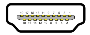
Pin Configuration and Descriptions
HDMI connectors have 19 pins (Type A, the most common). Below is the pin configuration for a standard HDMI Type A connector:
| Pin Number | Signal Name | Description |
|---|---|---|
| 1 | TMDS Data2+ | Positive signal for TMDS (Transition Minimized Differential Signaling) channel 2 |
| 2 | TMDS Data2 Shield | Shield for TMDS channel 2 |
| 3 | TMDS Data2- | Negative signal for TMDS channel 2 |
| 4 | TMDS Data1+ | Positive signal for TMDS channel 1 |
| 5 | TMDS Data1 Shield | Shield for TMDS channel 1 |
| 6 | TMDS Data1- | Negative signal for TMDS channel 1 |
| 7 | TMDS Data0+ | Positive signal for TMDS channel 0 |
| 8 | TMDS Data0 Shield | Shield for TMDS channel 0 |
| 9 | TMDS Data0- | Negative signal for TMDS channel 0 |
| 10 | TMDS Clock+ | Positive signal for TMDS clock |
| 11 | TMDS Clock Shield | Shield for TMDS clock |
| 12 | TMDS Clock- | Negative signal for TMDS clock |
| 13 | CEC | Consumer Electronics Control for device communication |
| 14 | Reserved (N.C.) | Reserved for future use |
| 15 | SCL | I2C serial clock for DDC (Display Data Channel) |
| 16 | SDA | I2C serial data for DDC |
| 17 | DDC/CEC Ground | Ground for DDC and CEC |
| 18 | +5V Power | +5V power supply for HDMI devices |
| 19 | Hot Plug Detect | Detects the presence of an HDMI device |
Usage Instructions
How to Use HDMI in a Circuit
HDMI is primarily used as a plug-and-play interface, requiring no additional circuitry for basic operation. However, when integrating HDMI into a custom design, such as a development board or embedded system, consider the following:
- Connector Selection: Choose the appropriate HDMI connector type (Type A, C, or D) based on your application.
- Signal Integrity: Use high-quality PCB traces and impedance-controlled routing for TMDS signals to prevent signal degradation.
- Power Supply: Ensure the +5V pin provides a stable power source, typically from a 5V regulator.
- Hot Plug Detect: Implement circuitry to detect when an HDMI device is connected.
- EDID and DDC: Use the I2C lines (SCL and SDA) to communicate with the display's EDID (Extended Display Identification Data) for resolution and feature negotiation.
Important Considerations and Best Practices
- Cable Quality: Use certified HDMI cables to ensure compatibility and performance, especially for high resolutions like 4K or 8K.
- Signal Length: For long cable runs, consider using active HDMI cables or extenders to maintain signal quality.
- Version Compatibility: Ensure the HDMI version of your source and display devices supports the desired features (e.g., HDR, 120Hz refresh rate).
- Electromagnetic Interference (EMI): Use proper shielding and grounding to minimize EMI in high-speed HDMI signals.
Example: Connecting HDMI to an Arduino UNO
While the Arduino UNO does not natively support HDMI, you can use an HDMI shield or adapter to interface with HDMI devices. Below is an example of using an Arduino UNO to control an HDMI device via the CEC (Consumer Electronics Control) pin:
#include <Wire.h> // Include the Wire library for I2C communication

#define CEC_PIN 13 // Define the pin connected to the HDMI CEC line

void setup() {
  pinMode(CEC_PIN, OUTPUT); // Set the CEC pin as an output
  digitalWrite(CEC_PIN, LOW); // Initialize the CEC line to LOW
  Serial.begin(9600); // Start serial communication for debugging
  Serial.println("HDMI CEC Control Initialized");
}

void loop() {
  // Example: Send a simple CEC command (e.g., power on a device)
  digitalWrite(CEC_PIN, HIGH); // Send a HIGH signal on the CEC line
  delay(100); // Wait for 100ms
  digitalWrite(CEC_PIN, LOW); // Set the CEC line back to LOW
  delay(5000); // Wait for 5 seconds before sending the next command
}
Note: This is a simplified example. For full HDMI CEC functionality, use a dedicated HDMI CEC library or IC.
Troubleshooting and FAQs
Common Issues
No Signal on Display
- Cause: Loose or damaged HDMI cable.
- Solution: Check the cable connections and replace the cable if necessary.
Flickering or Artifacts on Screen
- Cause: Poor signal quality due to long cable length or interference.
- Solution: Use a shorter or higher-quality cable. Ensure proper shielding.
Audio Not Working
- Cause: Incorrect audio settings on the source or display device.
- Solution: Verify the audio output settings on the source device and ensure the display supports audio.
HDMI Device Not Detected
- Cause: Hot Plug Detect (HPD) signal not functioning.
- Solution: Check the HPD pin connection and ensure the +5V power supply is stable.
FAQs
Can HDMI cables be used for Ethernet?
- Yes, HDMI cables with Ethernet support can transmit network data, but both devices must support HDMI Ethernet Channel (HEC).
What is the maximum resolution supported by HDMI?
- HDMI 2.1 supports up to 10K resolution at 120Hz.
Can I use an HDMI splitter to connect multiple displays?
- Yes, but ensure the splitter supports the required resolution and refresh rate for all connected displays.
Is HDMI backward compatible?
- Yes, newer HDMI versions are backward compatible with older versions, but advanced features may not be available.