
How to Use MCP1700 LDO: Examples, Pinouts, and Specs
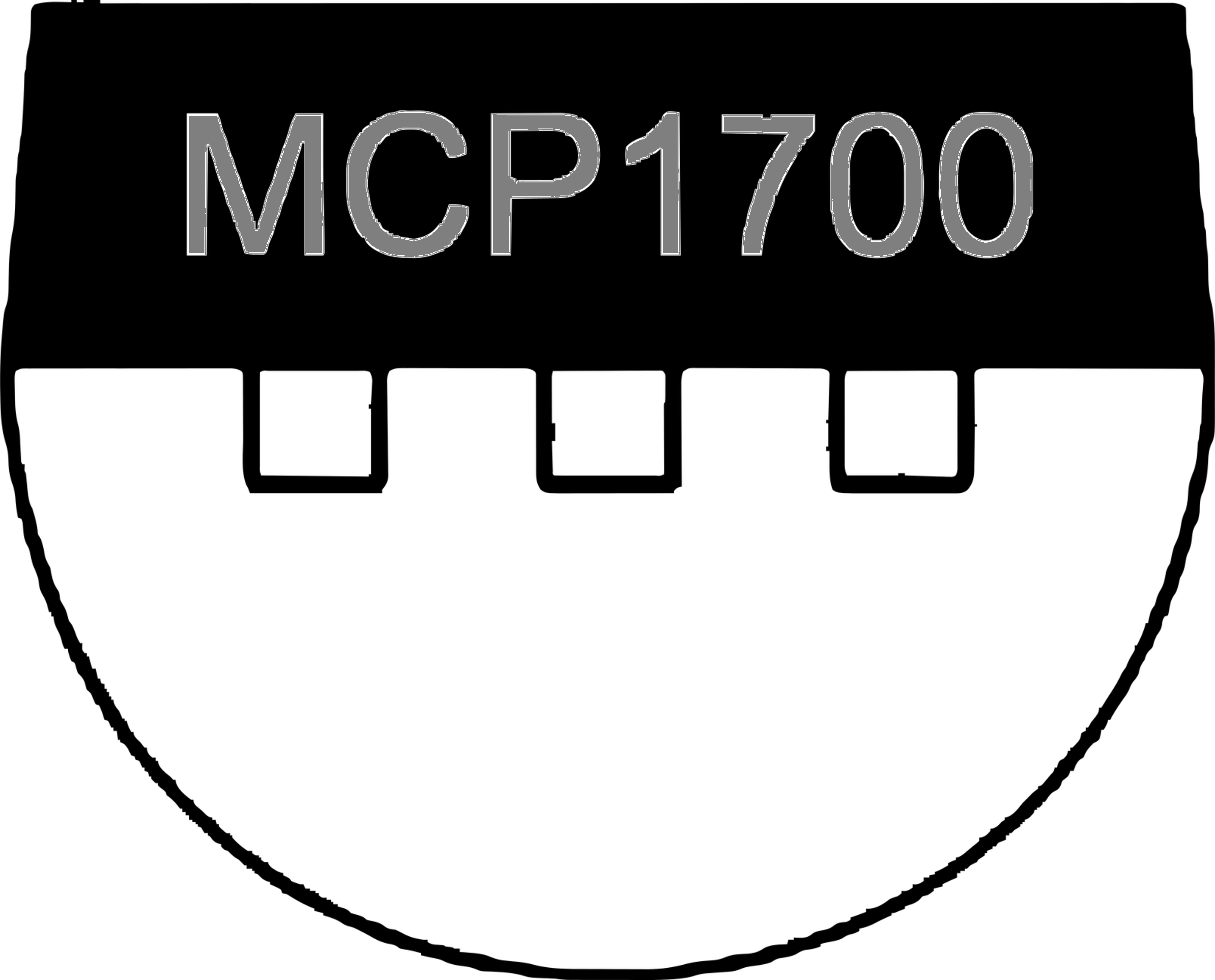
 Design with MCP1700 LDO in Cirkit Designer
Introduction
The MCP1700 is a low-dropout (LDO) voltage regulator manufactured by Bridgold. It is designed to provide a stable output voltage with an exceptionally low quiescent current, making it an excellent choice for battery-powered and energy-efficient applications. The MCP1700 can deliver up to 250 mA of output current and operates over a wide input voltage range. Its low dropout voltage and built-in thermal shutdown protection ensure reliable performance in various electronic circuits.
Explore Projects Built with MCP1700 LDO
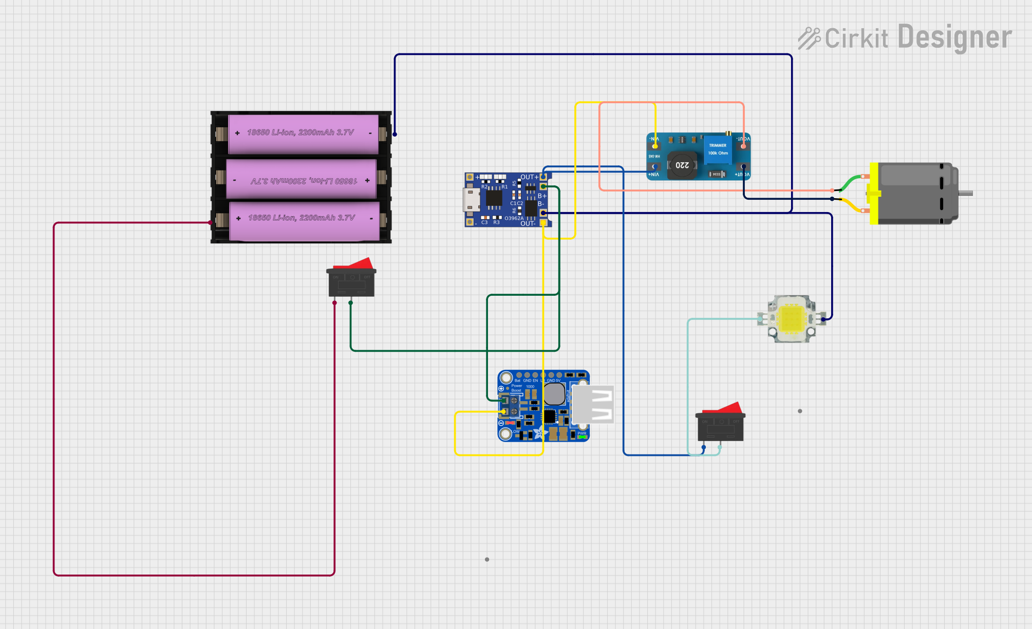
 Open Project in Cirkit Designer
 Open Project in Cirkit Designer
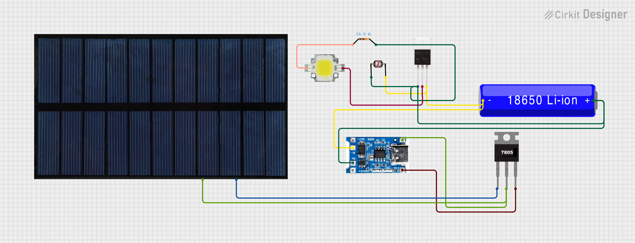 Open Project in Cirkit Designer
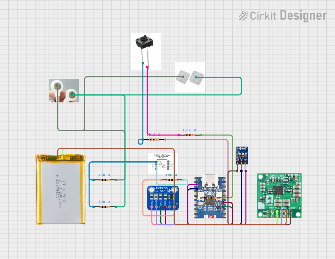 Open Project in Cirkit Designer
Explore Projects Built with MCP1700 LDO
Open Project in Cirkit DesignerOpen Project in Cirkit DesignerOpen Project in Cirkit DesignerOpen Project in Cirkit DesignerCommon Applications
- Battery-powered devices (e.g., remote sensors, wearables)
- Low-power microcontroller systems
- Portable electronics
- IoT devices
- Power supply regulation for analog and digital circuits
Technical Specifications
Key Specifications
| Parameter | Value |
|---|---|
| Manufacturer | Bridgold |
| Part Number | MCP1700 |
| Output Current | Up to 250 mA |
| Input Voltage Range | 2.3 V to 6.0 V |
| Output Voltage Options | 1.2 V, 1.5 V, 1.8 V, 2.5 V, 3.0 V, 3.3 V, 5.0 V |
| Dropout Voltage | 178 mV (typical at 250 mA load) |
| Quiescent Current | 1.6 µA (typical) |
| Operating Temperature Range | -40°C to +125°C |
| Protection Features | Thermal shutdown, short-circuit protection |
Pin Configuration and Descriptions
The MCP1700 is available in multiple package types, such as SOT-23 and TO-92. Below is the pin configuration for the SOT-23-3 package:
| Pin Number | Pin Name | Description |
|---|---|---|
| 1 | VIN | Input voltage (2.3 V to 6.0 V) |
| 2 | GND | Ground |
| 3 | VOUT | Regulated output voltage |
For the TO-92 package:
| Pin Number | Pin Name | Description |
|---|---|---|
| 1 | VOUT | Regulated output voltage |
| 2 | GND | Ground |
| 3 | VIN | Input voltage (2.3 V to 6.0 V) |
Usage Instructions
How to Use the MCP1700 in a Circuit
- Input Voltage: Connect the input voltage (VIN) to the MCP1700's VIN pin. Ensure the input voltage is within the range of 2.3 V to 6.0 V.
- Output Voltage: Connect the load to the VOUT pin. The output voltage will be regulated to the specified value (e.g., 3.3 V or 5.0 V).
- Ground Connection: Connect the GND pin to the circuit's ground.
- Capacitors:
- Place a 1 µF ceramic capacitor close to the VIN pin to stabilize the input voltage.
- Place a 1 µF ceramic capacitor close to the VOUT pin to ensure stable output voltage and reduce noise.
Important Considerations
- Thermal Management: Ensure adequate heat dissipation if the MCP1700 is operating near its maximum current rating (250 mA).
- Input Voltage: Avoid exceeding the maximum input voltage of 6.0 V to prevent damage to the regulator.
- Load Current: Do not exceed the maximum output current of 250 mA.
- Capacitor Selection: Use low-ESR ceramic capacitors for optimal performance.
Example: Using MCP1700 with Arduino UNO
The MCP1700 can be used to power an Arduino UNO or other microcontroller boards. Below is an example circuit and code to demonstrate its usage:
Circuit Diagram
- Connect a 5 V battery to the MCP1700's VIN pin.
- Connect the MCP1700's VOUT pin to the Arduino UNO's 5 V pin.
- Connect the GND pin of the MCP1700 to the Arduino's GND pin.
Example Code
// Example code for Arduino UNO powered by MCP1700 LDO regulator
// This code blinks an LED connected to pin 13

void setup() {
  pinMode(13, OUTPUT); // Set pin 13 as an output
}

void loop() {
  digitalWrite(13, HIGH); // Turn the LED on
  delay(1000);            // Wait for 1 second
  digitalWrite(13, LOW);  // Turn the LED off
  delay(1000);            // Wait for 1 second
}
Troubleshooting and FAQs
Common Issues and Solutions
No Output Voltage:
- Verify that the input voltage is within the specified range (2.3 V to 6.0 V).
- Check the connections to ensure proper wiring of VIN, VOUT, and GND.
- Ensure the input capacitor (1 µF) is properly connected to stabilize the input voltage.
Output Voltage is Unstable:
- Verify that the output capacitor (1 µF ceramic) is connected close to the VOUT pin.
- Check for excessive noise or ripple on the input voltage.
Overheating:
- Ensure the load current does not exceed 250 mA.
- Improve heat dissipation by using a heatsink or ensuring proper airflow around the component.
Short Circuit or Overload:
- The MCP1700 includes short-circuit protection. Remove the short circuit or reduce the load to restore normal operation.
FAQs
Q: Can I use electrolytic capacitors instead of ceramic capacitors?
A: While electrolytic capacitors can be used, ceramic capacitors are recommended due to their low ESR, which ensures better stability and performance.
Q: What happens if the input voltage exceeds 6.0 V?
A: Exceeding the maximum input voltage can damage the MCP1700. Always ensure the input voltage stays within the specified range.
Q: Can the MCP1700 power a microcontroller directly?
A: Yes, the MCP1700 can provide a stable voltage to power microcontrollers, provided the total current draw does not exceed 250 mA.
Q: Is the MCP1700 suitable for high-frequency switching circuits?
A: The MCP1700 is designed for low-power, low-frequency applications. For high-frequency circuits, consider using a switching regulator instead.
This concludes the documentation for the MCP1700 LDO voltage regulator.